RoofViews

Building Science

Edge Metal Design Wall Zones 4 and 5

By James R Kirby

April 19, 2019

Edge metal

Keeping water out of a building is undoubtedly the primary function of a roof system. But one could argue that ensuring a building's roof stays in place during high-wind events is equally important. Let's face it, without a roof, it's hard to keep water out! This blog takes a look at one of the subsets of wind design of roof systems: Wall Zones 4 and 5 and their relationship with roof perimeters.

Introduction

Architects, specifiers, and roof system designers are generally focused on the wind-uplift capacity of the roof system itself. Wind resistance of perimeter edges and parapets might not be front of mind, especially given the myriad roof-system Approval Listings that can be found through DORA, FM, and UL. However, rooftop perimeters and corner areas are most vulnerable to high wind, and perimeter edge metal and copings are part of the first line of defense. Codes now include wind-design and system testing for edge metal and copings. FM also just recently (late 2021) updated RoofNav's Wind Rating Calculator to include fascia, copings, and gutters.

Edge metal and copings

The term 'edge metal' encompasses three foundational shapes that are used at a roof's perimeter: L-shaped metal, gravel stop metal, and copings for parapets. The figures below show generic shapes; ones that are often contractor-fabricated. Additionally, there are many manufacturers that provide edge metal. Some of the manufacturer-fabricated shapes are similar to those shown below. However, some are a bit more distinct and some are extruded to achieve more unique shapes.

Graphic adapted from National Roofing Contractors Association

Some examples of GAF's metal details are shown here:

Steel and aluminum are common materials used for edge metal shapes and copings. Some are galvanized; some are painted. Commonly used thicknesses range from 20 gauge to 24 gauge for steel and 0.032" to 0.040" for aluminum. The continuous cleat is typically one gauge thicker than the edge metal and coping.

Why is wind design of edge metal important?

The roofing industry has been investigating high-wind events, primarily through a group called the Roofing Industry Committee on Weather Issues (RICOWI). RICOWI was established in 1990 and has published numerous reports based on post-wind-event investigations of damage caused by hurricanes. RICOWI's most recent report, released November 19, 2019, covers their investigation of the damage caused by Hurricane Michael. RICOWI has published five reports covering their investigations of 6 hurricanes since 2004.

One of the most consistent conclusions throughout the series of 5 reports of post-event investigations is that the majority of localized roof damage and roof system failures due to high winds commonly begin at perimeters and corners. This is not surprising as the highest wind loads are at rooftop perimeters and corners. This blog about wind design and ASCE-16, among other topics, discusses the process and factors used to determine wind loads, and it provides additional information about roof zone layout.


Localized roof damage and roof system failures due to high winds commonly begin at perimeters and corners.

Not recognizing the importance of edge metal design relative to the overall wind performance of a roof system can result in edge metal installations that may not have the appropriate wind-resistance capacity. This could possibly result in localized damage and/or system failures, even when the roof system (i.e., deck, insulation, membrane) is appropriately designed for design wind loads.

The following information is intended to supplement the wind design concepts that were discussed in GAF's earlier blog about wind design and ASCE 7-16.

Roof and Wall Zones

Wind design of metal edges and copings includes an upward and an outward component, unlike the primary roof system which includes an upward component only. (The Edge Metal Testing section of this blog has more information on that topic). ASCE 7 calls the outward pressures acting on metal edges and copings Wall Zones 4 and 5. Wall Zone 4 correlates and is aligned with Roof Zone 2 (the perimeter zones), and Wall Zone 5 is aligned with Roof Zone 3 (the corner zones). The figure shows one example of a building's roof and wall zones. Case studies from this blog provide more specific information related to the figure below.

Roof and Wall Zone

What do the codes say?

The International Building Code (IBC) includes requirements for determining the wind-load capacity for metal edges and copings. This requirement has been included since the 2003 version of the IBC. In other words, edge metal and copings should have wind-resistance capacities greater than the design wind pressures. This concept is just like wind design for the primary roof system—the capacity of the system needs to be greater than the anticipated loads.

Chapter 15, Section 1504.5 from the 2015 IBC includes requirements for determining the capacity of metal edges and copings.

"1504.5 Edge securement for low-slope roofs. Low-slope built-up, modified bitumen and single-ply roof system metal edge securement, except gutters, shall be designed and installed for wind loads in accordance with Chapter 16 and tested for resistance in accordance with Test Methods RE-1, RE-2 and RE-3 of ANSI/SPRI ES-1, except Vu1t wind speed shall be determined from Figure 1609A, 1609B, or 1609C as applicable."

Chapter 16 of the IBC indirectly includes requirements for determining the wind loads acting on metal edges and copings. In Section 1609.1 Applications, the IBC states "Buildings, structures and parts thereof shall be designed to withstand the minimum wind loads…" The "parts thereof" encompasses metal edges and copings. The requirement in Chapter 15 to design and install metal edges and copings means the outward pressures for Wall Zones 4 and 5 need to be determined.

It's worth noting that the scope of the ANSI/SPRI ES-1 test method does not include gutters, which is why gutters are specifically excluded in the code language through 2018. However, SPRI, in 2016, published ANSI/SPRI GT-1, Test Standard for Gutters, which was first included in model codes in the 2021 IBC.

Edge metal testing

Determining the design wind pressures (in pounds per square foot) for Wall Zones 4 and 5 is generally the responsibility of the design professional, such as the architect or structural engineer. On the other hand, determining the capacity of metal edges and copings is generally the responsibility of the manufacturer, which may be a manufacturing company or a roofing contractor that fabricates their own metal edges, coping, and clips and cleats.

The IBC specifically lists ANSI SPRI ES-1, Test Standard for Edge Systems Used with Low Slope Roofing, as the test method to be used to determine capacity for metal edges and copings. ES-1 includes three (3) test methods (RE-1, RE-2, RE-3), each for a different edge condition.

  • The RE-1 test method is for 'dependently terminated roof membrane systems'. Essentially, a mechanically attached or ballasted membrane is considered to be dependently terminated if a "peel stop" or row of fasteners is not included within 12" from the roof edge. Without a peel stop or a row of fasteners close to the edge of the roof, the edge metal is acting as the mechanical attachment of the perimeter of the membrane. (The RE-1 figure below is rotated clockwise 115 degrees to show the as-tested configuration of the metal edge. ES-1 presumes a ballasted or mechanically attached membrane will flutter and apply load to the metal edge at 25 degrees. The rotated configuration accommodates a hanging load.)

  • The RE-2 test method is for essentially all metal edge types as long as the "horizontal component" is 4" wide or less.

  • The RE-3 test method is for copings, and RE-3 includes two tests. One test includes an upward load and a 'face' load; the second test includes an upward load and the 'back leg' load.

The wind-resistance capacity of metal edges and copings is provided in "pounds per square foot" (psf). This is appropriate because the design wind pressures are also in PSF values which makes the comparison of design wind pressures to wind-resistance capacity simple.

Where to find Approval Listings for edge metal

Similar to approval listings for roof systems, there are approval listings for metal edges and copings. Approval Listings are found on FM's RoofNav and UL's Product IQ. An account (free) is required for both. Additionally, NRCA has Approval Listings for contractor-fabricated metal edges and copings which are housed on UL's Product IQ and Intertek's Directory of Building Products.

UL

Knowing UL's Category Control Number is key to navigating UL's Product IQ. . For metal edges and coping, UL's Category Control Number is "TGJZ". After logging in, performing a search using "TGJZ" provides a list of the manufacturers that have Approval Listings with UL. Clicking on GAF's Approval Listings allows users to easy find rated Roof-edge Systems, Metal, for Use with Low-slope Roofing Systems.

Within UL's TGJZ category, GAF has 16 metal-edge products rated using the RE-2 test method and 8 coping products rated using the RE-3 test method. For example (as shown in item 3 in the screen capture above), GAF's M-Weld Gravel Stop MB Fascia B made with aluminum is rated "190 psf". That means this product can be used when the design wind pressures, which include a safety factor, for Wall Zones 4 and 5 are less than or equal to 190 psf.

FM's RoofNav

Within RoofNav, Approval Listings for metal edges and copings can be found under "Product Search" using the "Flashing" category. Most likely, users of RoofNav are familiar with the "Assembly Search" function which is regularly used to locate roof systems based on their wind-uplift ratings.

The search can be further refined within "Subcategory" by selecting Expansion Joint, Gutter, or Perimeter Flashing.

Currently, GAF has 59 Approval Listings in RoofNav: 12 for Coping, 41 for Fascia, and 6 for Gutter products. A screen capture from RoofNav shows GAF's first 20 products.

Looking closely at the Listing, the EverGuard EZ Fascia AR – Steel provides detailed information about the product itself and the installation requirements. As shown below, the listing includes multiple Ratings (i.e., wind-uplift capacity) based on material type and thickness, and face height.

While the Listing is for a steel fascia, an aluminum fascia is also shown in the detailed information. It's important to note that the chart with the "steel" listing's detailed information is the same chart that is available for EverGuard EZ Fascia AR – Aluminum, as well. Therefore, it's prudent for designers and specifiers to provide appropriate information in the specification to avoid mis-communiction about intended product use.

Take note of the material and gauge of the "retainer" (i.e., the continuous cleat). The continuous cleat is required to be 0.50 aluminum, regardless of fascia material type for this Listing. Because the strength of the cleat is a significant factor to the overall wind-uplift capacity of the metal edge (or coping), increasing the thickness of the cleat proves to be an effective method to increase performance.

FM RoofNav and Edge Securement

FM announced on its website on October 28, 2021 that "The Wind Ratings Calculator has been updated to return separate flashing ratings for roofs." The red-highlighted area shows the required capacity for Fascia, Coping, and Gutter products.

Comparison of the Minimum Wind Uplift Approval Ratings Needed (1-75, 1-90) to the Perimeter and Corner Ratings of the EverGuard EZ Fascia shows that each product type provides the required capacity, and in most cases the required capacity greatly exceeds the required rating.
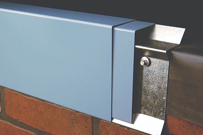
Load Path

The 3 test methods included in ANSI/SPRI ES-1 standard determine the wind-resistance capacity of edge metal attached to a substrate. In other words, the measured capacity (Rating) is of the metal edge or coping attached to the wood blocking; the tests do not measure the capacity of the attachment of the wood blocking to any substrate. The National Roofing Contractors provide information on this topic. The NRCA Roofing Manual: Membrane Roof Systems—2019, on page 289 states:

"Wood Nailers and Blocking: Many of the construction details illustrated in this manual depict wood nailers and blocking at roof edges and other points of roof termination. Wood nailers must be adequately fastened to the substrate below to resist uplift loads. This especially is true at parapet walls/copings and roof edges where edge-metal shapes are fastened to wood blocking.

Among other advantages, the nailers provide protection for the edges of rigid board insulation and provide a substrate for anchoring flashing materials. Wood nailers should be a minimum of 2 x 6 nominal-dimension lumber. To provide an adequate base, nailers should be securely attached to a roof deck, wall and/or structural framing. In the design of specific details for a project, a designer should describe and clearly indicate the manner in which wood nailers and/or blocking should be incorporated into construction details. A designer should specify the means of attachment, as well as the fastening schedule for all wood nailers and blocking."

To that end, FM Global Property Loss Prevention Data Sheet 1-49, Perimeter Flashings, provides a number of recommendations for anchoring wood blocking to various types of walls and structural framing. One example of a roof/wall intersection shows the bottom nailer bolted to the bar joists to ensure an adequate load path.

In Summary

Architects, specifiers, and roof system designers are required by code (always check specific local requirements) to determine wind loads not only for the primary roofing system, but for the metal edges and copings as well. Manufacturers and fabricators are responsible for determining the wind-uplift capacity of their metal edge and coping products, as well as their primary roofing systems.

Given the relatively new requirements in the IBC for edge securement, designers, consultants, and specifiers should become familiar with both UL's and FM's approval listings for metal edges and copings. Manufacturers of metal edge and coping products are available to assist designers with selection of edge securement.

About the Author

James R. Kirby, AIA, is a GAF building and roofing science architect. Jim has a Masters of Architectural Structures and is a licensed architect. He has over 25 years of experience in the roofing industry covering low-slope roof systems, steep-slope roof systems, metal panel roof systems, spray polyurethane foam roof systems, vegetative roof coverings, and rooftop photovoltaics. He understands the effects of heat, air, and moisture movement through a roof system. Jim presents building and roofing science information to architects, consultants and building owners, and writes articles and blogs for building owners and facility managers, and the roofing industry. Kirby is a member of AIA, ASTM, ICC, MRCA, NRCA, RCI, and the USGBC.

Related Articles

Commercial Roof
Building Science

IBC and FM—What's the Difference When it Comes to Wind Design?

IntroductionWind design of roof systems can be confusing from an engineering perspective. Wind design can also be confusing because the International Building Code (IBC) provides specific requirements, but so does Factory Mutual (FM). If FM is specified, do the IBC requirements need to be followed? What is the wind-design strategy for FM-insured and non-FM-insured buildings? This blog will discuss the following:IBC is a model code; FM is an insurance companyCompliance with the local building code is a legal requirement; FM is elective (a building owner has the ability to select their insurance carrier)IBC references the ASCE 7 standard; FM provides wind-design methodology via the Ratings Calculator and Assembly Search functions within RoofNavFM-insured buildings must comply with both the IBC and FM requirementsSpecifying "FM" could trigger the "FM process" unknowingly for non-FM insured buildingsWhat is the issue?In roofing specifications, architects have been referencing Factory Mutual (FM) for many decades, especially when it comes to wind design of commercial roofing systems. "Meet FM requirements," "Provide a 1-90 roof system," or just simply "Meet FM" are phrases inserted into specifications. Do these phrases supplant the need to follow the wind-design requirement of the International Building Code (IBC)? (Spoiler alert: The answer is a resounding "NO".)The BasicsThe IBC is a model code, developed by the International Code Council. A model code, such as the IBC, is intended to be adopted by municipalities (e.g., state, city) as the locally enforced building code. The model code can be adopted as-is, or with language removed, with language added, or both. The local building code is enforced through local building code officials. And, very importantly, meeting the local building code is a legal requirement and there can be ramifications when the local building code is not met.Commercial buildings are required to meet the IBC as adopted and amended by the local jurisdiction. For wind design, the IBC requires a roof system be designed based on ASCE 7, Minimum Design Loads for Buildings and Other Structures. (More on the specifics later.)FM Global is an insurance company and a purveyor of design and installation documents for roof systems (e.g., Loss Prevention Data Sheets 1-28, Wind Design). FM Approvals is a testing facility, a third-party certification body, and a developer of Approval Standards (e.g., FM 4470, Single-Ply, Polymer-Modified Bitumen Sheet, Built-Up Roof (BUR) and Liquid Applied Roof Assemblies for use in Class 1 and Noncombustible Roof Deck Construction). FM Approvals also maintains RoofNav (www.RoofNav.com), which provides access to FM Approved roofing systems and related installation recommendations from FM Global. RoofNav is likely the FM tool that is frequently used by architects and roof system designers who are searching for and selecting approved roof systems. This is why many architects and specifiers include some reference to FM in roof system specifications.IBC Wind Design MethodModel building codes, such as the 2018 IBC, when adopted by a local jurisdiction, become the legal requirements for construction. The IBC specifically states, "The I-Codes, including this International Building Code, are used in a variety of ways in both the public and private sectors. Most industry professionals are familiar with the I-Codes as the basis of laws and regulations in communities across the U.S. and in other countries." A more succinct way of stating this is—the local building code is the law.Within the IBC, the building code requirements for roofing and rooftop construction are found in Chapter 15, Roof Assemblies and Rooftop Structures. Section 1501.1, Scope, states "The provisions of this chapter shall govern the design, materials, construction and quality of roof assemblies, and rooftop structures." Wind resistance of roof systems is included in Section 1504, Performance Requirements, and Section 1504.1, Wind resistance of roofs, requires roofs be designed for wind loads according to Chapter 16, Structural Design.Section 1609, Wind Loads, incorporates by reference the standards set forth in ASCE 7; this section includes the following language."1609.1.1 Determination of wind loads. Wind loads on every building or structure shall be determined in accordance with Chapters 26 to 30 of ASCE 7."It's worth noting that the version (i.e., year of publication) of ASCE 7 is not specified in the body of the code; versions of referenced standards are found in Chapter 35.The key point is that the IBC directs users to ASCE 7 to determine design wind pressures (DWP) for roof systems.To continue a bit deeper into the 2018 IBC, Section 1504.3 is the directive to designers to design roofs to resist design wind pressures."1504.3 Wind resistance of non ballasted roofs. Roof coverings installed on roofs in accordance with Section 1507 that are mechanically attached or adhered to the roof deck shall be designed to resist the design wind load pressures for components and cladding in accordance with section 1609.5.2."It's important to recognize that Section 1504.3 specifically ties the wind design of nonballasted roofs to ASCE 7 by referencing a subsection of Section 1609.Additionally, Section 1504.3.1 is the directive to manufacturers to test roof systems to determine wind uplift capacity."1504.3.1 Other roof systems. Built-up, modified bitumen, fully adhered or mechanically attached single-ply roof systems, metal panel roof systems applied to a solid or closely fitted deck and other types of membrane roof coverings shall be tested in accordance with FM 4474, UL 580 or UL 1897."This section provides 3 code-approved test methods to choose from to perform wind-uplift-capacity testing.FM 4474, American National Standard for Evaluation of Simulated Wind Uplift Resistance of Roof Assemblies Using Static Positive and/or Negative Differential PressuresUL 580, Standard for Tests for Uplift Resistance of Roof AssembliesUL 1897, Standard for Uplift Tests for Roof Covering SystemsThese tested systems are found in Approval Listings from organizations like FM, UL, and SPRI. These two videos provide more information about FM Approval's RoofNav and SPRI's Directory of Roofing Assemblies.What's NOT Stated in the IBCNothing in the model code sections referenced here or any other related model code sections within IBC contains a provision that allows a wind-design method other than ASCE 7 to be used. In other words, using FM's RoofNav for wind design of roof systems is not a replacement for following building code requirements that mandate the use of ASCE 7. Of course, designers should always check with the specific requirements of the local building code to determine if the use of FM's RoofNav is allowed for code compliance.FMWe've established that FM Global is an insurance company that provides installation recommendations and FM Approvals provides design information, as well as FM-approved listings. In order to receive an FM Approval Listing, a roof system must be tested in accordance with FM 4470, Single-Ply, Polymer-Modified Bitumen Sheet, Built-Up Roof (BUR) and Liquid Applied Roof Assemblies for use in Class 1 and Noncombustible Roof Deck Construction.FM 4470 includes a battery of tests intended to help determine the long-term performance of a roof system (clearly an important issue for an insurance carrier!).FM 4470 includes the following mandatory tests to be performed:Combustibility (from above and below the roof deck)Wind uplift (FM 4474 is the test method used to determine wind uplift capacity)Hail resistanceWater leakageFoot trafficCorrosionSusceptibility to heat damageFM 4470 also includes requirements for a manufacturer's in-house quality control program that includes an audit program, field inspections during installation, and additional manufacturer responsibilities if products' construction or components are revised.The use of FM 4470 results in a roof system with a "1-60" or "1-75" listing, for example. The "1" represents the roof system is Class 1 for fire resistance (combustibility) from below the deck. The second (e.g., 60, 75) represents the wind-uplift capacity (in pounds per square foot) of the roof system.It is important to recognize that FM 4470 is not listed as one of the test methods for wind-uplift capacity in the 2018 IBC, which means the IBC does not require a roof system to be FM-approved!FM 4474, American National Standard for Evaluation of Simulated Wind Uplift Resistance of Roof Assemblies Using Static Positive and/or Negative Differential Pressures, is a test method to determine wind uplift capacity of roof systems. As noted previously, FM 4474 is the wind-uplift test method that is required to be used within FM 4470 for an FM Approval Listing.FM-insured buildingsBuildings that are FM insured are commonly required by FM to use a roof system that has an FM Approval Listing. More specifically, roof systems intended to be used on FM-insured buildings should use RoofNav to determine wind loads (via the RoofNav Ratings Calculator) and find Approved roof systems (via the RoofNav Assembly Search).Non FM-insured BuildingsTo broadly say "Meet FM" or "Meet FM requirements" in a spec could be interpreted to mean—for non-FM insured buildings—that the wind-design process, deck securement, and roof system installation should follow ALL of the specific FM processes and recommendations that are used for FM-insured buildings.As the architect or specifier working on a building that is not insured by FM, is the vague specification language truly intended to bring the entire "FM process" into the wind design and installation of a roof system? Probably not. It is more likely the vague specification language referencing FM is intended to be a way to state that the assembly must meet local building code requirements for wind design.Saying "Meet FM" or "Meet FM requirements" does not preempt or override the requirements of the IBC, as adopted by local building code, that are legally required to be performed by the Architect of Record when it comes to wind design of roof systems. (Additional information about code requirements for wind design can be found here.)ConclusionThe IBC, as adopted by local building codes, is required by law and references ASCE 7 as the standard to be used for determining design wind pressures for roof systems. The IBC does not include FM's wind-design process (e.g., RoofNav's Ratings Calculator and Assembly Search functions) for determining DWPs. Vague specification language referencing FM may unnecessarily bring the FM wind-design process into play.The IBC also provides 3 test methods for determining wind-uplift capacity of roof systems—UL 580, UL 1897, and FM 4474. It is important to recognize that FM 4474 is a test method used by manufacturers to determine wind-uplift capacity, and FM 4470 is a comprehensive standard covering many aspects of roof system performance. Specifying and only using FM's wind design process in lieu of following the wind-design requirements in IBC, as adopted by local building code, means the minimum legal requirements for wind design technically may not have been met.Understanding the roles that IBC and FM play in the roofing industry is key to understanding the role of the architect or specifier, and the manufacturer when it comes to wind design of roof systems.This blog is for informational purposes only and is not intended to be construed or used as professional design advice. Consult a design professional to ensure the suitability or code compliance of a particular roofing system for any particular structure.

By Authors James R Kirby

November 17, 2023

GAF Cedar City plant
Building Science

How will ASCE 7-16 affect the low-slope roofing industry? A Tale of Two Buildings

A common question being asked in the roofing industry is whether or not the 2016 version of ASCE 7 is going to increase the design wind pressures acting on a building. The answer is "yes" in many cases. So, the follow up question is "by how much?" And, that leads to the next question, "how much more capacity will roof systems be required to have when wind design follows ASCE 7-16?"This blog looks at 2 buildings of different sizes and heights in two cities in the U.S., one centrally located and one along the Gulf coast, and compares design wind pressures based on ASCE 7-10 and ASCE 7-16. By assessing the required roof-system capacity for all roof zones in conjunction with the increases in the size of roof zones, we can begin to put some real numbers to the question "by how much will ASCE 7-16 affect the low-slope roofing industry?"While analysis of two building types in two cities doesn't represent a significant study, this study offers an example of how the 2016 version of ASCE 7 is going to affect installed roofing systems over the next decade.Case StudiesDesign wind pressures (DWP) were determined for two building types in two cities. DWPs were based on varying the Risk Category and Exposure. The following table shows the building types, cities, variables, and constants.The big box store is 290' long x 169' wide x 24' tall, and the apartment building is 100' long x 40' wide x 55' tall. Wind speeds were determined using an online tool.DWPs can be determined by using proprietary third party methods (e.g., RoofNav), simplified calculation tools (e.g., RoofWindDesigner), or hand calculations following the methods within the ASCE 7 standard.For this case study, DWPs were determined using hand calculations via an Excel spreadsheet. The DWPs are slightly more refined since there was no rounding of wind speeds for ASCE 7-16. Both RoofNav and Roof Wind Designer round to the nearest 5 or 10 mph. The maps in ASCE 7-16 have been revised, not only from a wind speed perspective but from the number of wind isobars on the maps. The ASCE 7-16 maps are more refined which allows for more exact wind speed values.ASCE 7-10 Map, Risk Category II, showing a limited number of wind-speed isobars.ASCE 7-16 Map, Risk Category II, showing many additional wind-speed isobars relative to the ASCE 7-10 wind map shown in the above figure.In total, 72 different sets of DWPs were calculated. Buildings over 60' tall are designed the same in ASCE 7-16 as in ASCE 7-10; therefore, this article focuses on buildings less than 60' tall.Design Wind Pressure ResultsThe following charts provide the DWPs for each of the scenarios that were analyzed for this article.Design wind pressures based on ASCE 7-10 and ASCE 7-16 for a big box store in Kansas City, MO that is 24' tall.Design wind pressures based on ASCE 7-10 and ASCE 7-16 for a big box store in Mobile, AL that is 24' tall.Design wind pressures based on ASCE 7-10 and ASCE 7-16 for a 5-story apartment building in Kansas City, MO that is 55' tall.Design wind pressures based on ASCE 7-10 and ASCE 7-16 for a 5-story apartment building in Mobile, AL that is 55' tall.Comparing the 2010 and 2016 versionsThe primary intent of this article is to start generating data to help answer the question "how much did the DWP increase from the 2010 version to the 2016 version of ASCE 7?" Using the DWP calculated for each roof zone within each of the four scenarios, we calculated the percent increase in DWP per zone. The percent increases in DWP were calculated by dividing the ASCE 7-16 value with the corresponding ASCE 7-10 value for each roof zone. However, because there are 4 roof zones in ASCE 7-16 (and 3 roof zones in ASCE 7-10), both Roof Zones 1' and 1 were divided by the value for ASCE 7-10 Roof Zone 1 to determine the percent increase. Values in the following charts that are below 100% (shaded gray) indicate a reduction in DWP from ASCE 7-10 to 7-16.Percent increases in DWP per roof zone for a big box store in Kansas City, MO that is 24' tall, focusing on Exposure C values.Percent increases in DWP per roof zone for a big box store in Mobile, AL that is 24' tall, focusing on Exposure C values.Percent increases in DWP per roof zone for a 5-story apartment building in Kansas City, MO that is 55' tall, focusing on Exposure C values.Percent increases in DWP per roof zone for a 5-story apartment building in Mobile, AL that is 55' tall, focusing on Exposure C values.For the big box store scenarios, the percent increases in DWP per roof zone varies from 84% to 178%. The percent reductions (values less than 100%) are all in Roof Zone 1' while Roof Zones 1, 2, and 3 have increased DWP. As seen in the Figures, Roof Zone 1 percent increases are greatest while Roof Zone 3 increases are smallest.For the 5-story apartment building scenarios, the percent increases in DWP per roof zone varies from 84% to 177%. The percent increases in Roof Zone 1 are the largest. The percent reductions are all Roof Zone 1'.It is worth noting that the increases in Pressure Coefficients from ASCE 7-10 to 7-16 are, in fact, relatively indicative of the increases in DWP. For more on Pressure Coefficients and the wind design process.The case studies in this blog also show that the 2016 version of ASCE 7 imposes higher DWPs in Roof Zones 1, 2, and 3. However, given some of the substantial reductions in Roof Zone 1', it could be expected that installed roof system capacity may be lower. While that is hopeful, the roofing industry has a minimum-capacity backstop of 60 psf. This means that any calculated DWP at or below 60.0 psf (even for DWP values as low as 23 psf) will have a 60-psf-capacity roof assembly installed to meet building code requirements. The reality is many buildings are required to use a 60-psf-capacity roof system when in fact '60 psf' is more capacity than needed based on calculated DWPs.Let's take a closer look at one subset for each of the 4 scenarios.Example 1: Big Box; Central USThe big box store in KC, MO (Risk Category II, Exposure C) saw the DWP increase from 38 psf to 56 psf in Roof Zone 1 per ASCE 7-10 vs ASCE 7-16; and reduce to 32 psf in Roof Zone 1'. Regardless of the increases or decreases, a 60-psf-capacity roof should be installed in both Roof Zone 1 and Roof Zone 1' per 7-16, which is unchanged relative to ASCE 7-10.Roof zones and pressures for a 24' tall big box store in Kansas City, MO based on ASCE 7-10 using Risk Category II and Exposure C.Roof zones and pressures for a 24' tall big box store in Kansas City, MO based on ASCE 7-16 using Risk Category II and Exposure C.For Roof Zones 2 and 3, the DWPs are not only increased, but the sizes of the roof zones that require higher capacity are also increased. Roof Zone 2 per ASCE 7-10 required a 75-psf-capacity roof, and a 75-psf-capacity roof will be needed per ASCE 7-16. However, approximately 9% of the roof area will need a higher capacity because of the increase in roof zone size. The following chart shows roof area percentages based on the required roof system capacity for this scenario.Chart showing required roof capacity and the roof area (%) where each is required.Example 2: Big Box; Gulf CoastA big box store in Mobile, AL (Risk Category II, Exposure C) saw the DWP increase from 69 psf to 109 psf in Roof Zone 1 per ASCE 7-10 vs ASCE 7-16; and reduce to 63 psf in Roof Zone 1'. A 75-psf-capacity roof should be installed in Roof Zone 1', and higher-capacity roofs will be required in Roof Zones 1, 2, and 3 relative to ASCE 7-10.Roof zones and pressures for a 24' tall big box store in Mobile, AL based on ASCE 7-10 using Risk Category II and Exposure C.Roof zones and pressures for a 24' tall big box store in Mobile, AL based on ASCE 7-16 using Risk Category II and Exposure C.For Roof Zones 1, 2, and 3, the DWPs are not only increased, but the size of the roof zones that require higher capacity are also increased. A larger perimeter roof zone (combining Roof Zones 1 and 2) with higher required capacity is created (relative to 7-10). Approximately 30+% of the roof area will need a higher capacity. The following chart shows roof area percentages based on the required roof system capacity for this scenario.Chart showing required roof capacity and the roof area (%) where each is required.Example 3: 5-story; Central USThe 5-story apartment building in KC, MO (Risk Category II, Exposure C) saw the DWP increase from 45 psf to 66 psf in Roof Zone 1 per ASCE 7-10 vs ASCE 7-16; and reduce to 38 psf in Roof Zone 1'.However, because the method used to determine the sizes of roof zones in ASCE 7-16 is changed, Roof Zones 1' and 1 do not exist on this building! Decreases of DWP in Roof Zone 1' are rendered meaningless, and the lack of a Roof Zones 1' and 1 means the entire roof consists of only Roof Zones 2 and 3, the perimeter and corner roof zones.Roof zones and pressures for a 55' tall apartment building in Kansas City, MO based on ASCE 7-16 (top) and ASCE 7-10 (bottom) using Risk Cat II and Exposure C.The increases in DWPs for the roof zones significantly increase the roof system capacity requirements for this scenario. Almost the entire roof area will need a higher capacity roof. The following chart shows roof area percentages based on the required roof system capacity for this scenario.Chart showing required roof capacity and the roof area (%) where each is required.Example 4: 5-story; Gulf CoastThe 5-story apartment building in Mobile, AL (Risk Category II, Exposure C) saw the DWP increase from 81 psf to 129 psf in Roof Zone 1 per ASCE 7-10 vs ASCE 7-16; and reduce to 74 psf in Roof Zone 1'. Similar to Example 3, due to the size of the roof zones relative to the size of the roof, Roof Zones 1' and 1 do not exist in this scenario.Roof zones and pressures for a 55' tall apartment building in Mobile, AL based on ASCE 7-16 (top) and ASCE 7-10 (bottom) using Risk Cat II and Exposure C.The increases in DWP for the roof zones significantly increase the roof system capacity requirements for this scenario. The entire roof area will need a higher capacity. The following chart shows roof area percentages based on the required roof system capacity for this scenario.Performance versus PrescriptiveThe case studies in this analysis are presented using a performance method for wind design. That is, a specific DWP is determined for each roof zone and a roof system with appropriate capacity is selected for use in the associated roof zone. Another method that is often used in the roofing industry is a prescriptive method for wind design. The DWP for Roof Zone 1 (or Roof Zone 1' in certain localities) is used to select a roof system with an appropriate capacity for Roof Zone 1 (similar to a performance method), and then Roof Zones 2 and 3 use an installation method/layout that is prescriptively increased relative to Roof Zone 1 installation methods. Prescriptive installation methods for Roof Zones 2 and 3 are regularly used with mechanically attached (MA) roof systems, and for MA roofs, Roof Zone 2 increases are commonly 50% and Roof Zone 3 increases are commonly 100%.ConclusionASCE 7-16 DWPs are generally increasing relative to ASCE 7-10, but this impact is better understood by comparing the required roof system capacity for different building types and dimensions in different cities. Looking only at DWPs does not provide enough information; a comparison of required roof system capacities is needed. Not only did the DWPs change, but the methodology for determining the size of the perimeter and corner roof zones changed significantly in the new ASCE 7-16 version; the amount of roof area contained by the perimeter and corner roof zones increased. The case studies—of two buildings less than 60 ft tall in two cities—and corresponding analysis in this blog are just one additional small step to understanding how the ASCE 7-16 will affect wind design over the next decade.

By Authors James R Kirby

November 17, 2023

Roof
Building Science

Coatings and Liquid-applied Membranes— what's in a name?

Liquid-applied roof membranes (LAM) and roof coatings (aka, maintenance coatings) are not only here to stay, their use is on the rise. This blog takes a look at how the building code and the roofing industry generally differentiate between liquid-applied roof membranes and roof coatings. There is confusion because the intended use of each is different, yet many of the materials are the same for both applications. Here's what you need to know to help understand and differentiate between the two.IntroductionCoatings have been used in the construction and roofing industries for a very long time! They have been made from many different materials--from beeswax and pitch some 5000 years ago, to lacquers and varnishes just a couple thousand years ago, to our current polymer-based materials. According to the Roof Coating Manufacturers Association, "the most dramatic advance in coating properties has come in the past 40 years, with the development of polymers1." Polymer-based coatings are used on plaza decks, parking garages, balconies, playgrounds, and roofs, for example, to provide a level of water-resistance and an aesthetically pleasing surface. Polymer-based liquid-applied membranes are used as the water-proofing layer for new roofs, replacement roofs, and roof re-cover systems. The common polymer-based materials include acrylics, silicones, and urethanes. More information about these materials can be found here.The spotlight is on these types of polymers because the materials we use for coatings are quite often also being used as liquid-applied membranes. How do we categorize and define these different installations that have different intended uses when both applications use essentially the same set of materials? This blog takes a close look at each of these product categories—coatings and liquid-applied membranes—to find their similarities and differences. And hopefully to provide clarity around the use of terms and definitions of use.Market ShareIn 2017, The Freedonia Group published a research study titled, "Liquid-Applied Roof Coatings in the US by Product and Subregion." According to that report, 11.85 million squares (1.185 billion square feet) of liquid-applied roof coating were installed in 2016. Approximately 40% was installed in the South, with the remainder essentially evenly split between the Northeast, Midwest, and West regions.The Freedonia Group reported a number of key findings that help explain the increased use of coatings."The South will be the leading US regional market for roof coatings in 2021, boosted by a high level of interest in cool roofing products and in protecting roofs against storm damage.The West will see solid growth as communities amend building codes to mandate the use of cool roofing.Liquid-applied roof coating demand in the Midwest and Northeast will be supported by rising use of roof coatings to rejuvenate older roofs instead of engaging in more costly reroofing projects."Note: The Freedonia Group's report does not separate market share based on liquid-applied materials used as roof coatings versus liquid-applied materials used as roof membranes.The use of coatings and liquid-applied membranes is increasing for a number of additional reasons as well.The use of materials that can be applied at ambient temperature is welcomed by an installer. There are no super-heated materials or open flames therefore reducing specific safety concerns.Materials are typically provided in containers sized for easy transport to and from rooftops.Common low-cost installation tools are used—brooms, brushes, squeegees; and simple, low-cost spray equipment.Using liquid-applied membranes can reduce waste created by a tear off.These materials are commonly light colored so they are reflective to help improve energy efficiency.Depending on the design (intent) and application of polymer-based materials, they can be used to extend the life of an existing roof when used as a coating, or to provide a warranted or guaranteed, waterproofing roof covering when used as a liquid-applied membrane.Defining the TermsOne way to help sort out the difference between coatings and liquid-applied membranes is to understand current definitions used in the industry. The International Building Code (IBC) is a good place to start since it is considered to be consensus-based.International Building CodeThe International Building Code does include a definition for coating, but does not include a definition for liquid-applied membrane."ROOF COATING. A fluid-applied, adhered coating used for roof maintenance or roof repair, or as a component of a roof covering system or roof assembly."IBC's definition of Roof Coating tells us three things.Coatings are fluid-applied and adhered (to a substrate)Coatings are used for maintenance or repair "Roof Repair" is defined as "Reconstruction or renewal of any part of an existing roof for the purposes of correcting damage or restoring pre-damage condition." Coatings can be a component of a roof system or roof assembly (which are the same according to ICC's definitions) "Roof Assembly" is defined as "A system designed to provide weather protection and resistance to design loads. The system consists of a roof covering and roof deck or a single component serving as both the roof covering and the roof deck. A roof assembly can include an underlayment, a thermal barrier, insulation or a vapor retarder." "Roof Covering" is defined as "The covering applied to the roof deck for weather resistance, fire classification or appearance." "Roof Covering System" is a "Roof Assembly" per IBC. Realistically, IBC's definition of Roof Coating doesn't get us that much closer to differentiating coatings and liquid-applied membranes, except that coatings are intended for maintenance and repair. And per IBC's definition, coatings can be used for Roof Repairs to "correct damage or restore pre-damage condition," but that is not how coatings are generally intended to be used.Taking a look at how Chapter 15 of IBC is arranged gives a bit of insight into IBC's perspective on coatings and liquid-applied membranes. Section 1507, Requirements for Roof Coverings, has and continues to include all low-slope and steep-slope materials used as roof coverings that are recognized by the code. This includes materials such as asphalt, wood, and slate shingles, as well as modified bitumen and single-ply roofing (and myriad others). The ICC has always included a section specifically for Liquid-applied Roofing within Section 1507, but there has never been a section for Coatings (until this year—more on that in a bit). To that end, the IBC is essentially saying Liquid-applied Membranes are categorized similarly to all other membranes that are used as roof coverings and their intended use is for "weather resistance, fire classification or appearance" (from IBC's definition as shown above). Because liquid-applied membranes are considered to be roof coverings, roof systems that use a liquid-applied membrane need to be tested for fire, wind, and impact… like any traditional membrane roof system.The liquid-applied membrane subsection within Section 1507 includes ASTM standards for materials not only used as liquid-applied membranes, but it includes the polymer-based materials (e.g., acrylics, polyurethanes, silicones) that are also intended to be used as coatings. This led to confusion within the code requirements, specifically how code officials would enforce the application of a coating product on an existing roof--as a new roof or as a maintenance item.To help with clarification and code enforcement, new language was added to the 2018 IBC in the Reroofing Section that stated a roof coating can be applied to (essentially) any existing roof without triggering reroofing requirements. The 2015 IBC and earlier versions only stated that coatings could be applied over an existing Spray Polyurethane Foam without removing any existing roofs. The IBC 2018 code language is as follows:"Section 1511.3, Roof Replacement. Exception 4: The application of a new protective roof coating over an existing protective roof coating, metal roof panel, built-up roof, spray polyurethane foam roofing system, metal roof shingles, mineral-surfaced roll roofing, modified bitumen roofing or thermoset and thermoplastic single-ply roofing shall be permitted without tear off of existing roof coverings."The additional language in the 2018 IBC was a very important step in distinguishing between coatings and liquid-applied membranes.The I-Codes were further revised regarding coatings and liquid-applied membranes in the 2021 IBC; a new section was added--Section 1509, Roof Coatings. This was an entirely new section, and importantly, Roof Coatings are not a subsection within Section 1507, Roof Coverings. This strengthens the differentiation from a code perspective that coatings are not considered to be a new roof covering. However, the IBC 2021 remains without a definition for liquid-applied roofing or liquid-applied membrane. The code ultimately relies on manufacturers' intentions for their products as the differentiating factor between coatings and liquid-applied membranes.ASTMUnfortunately, ASTM D1079, "Standard Terminology Relating to Roofing and Waterproofing" does not define either term.Industry PerspectiveWhat does GAF, a leading supplier of both systems, say about each? From GAF's page, Liquid-Applied Coating Solutions, the following descriptions are provided."What is a Liquid Membrane Roofing System?A liquid-applied roofing system consists of multiple components that come together to form a fully adhered, seamless, and self-flashing membrane. Components include liquid applied coatings and mesh membranes to create a true liquid membrane system that preserves and protects the integrity of the building." Examples of some of the leading products can be found here."What is a Roof Coating System?Roof Coatings are designed for extending the life of existing structurally sound roofs. GAF Roof Coatings are specially formulated to extend the life of roofs while protecting them from damaging effects of weather and the environment such as UV light, water and wind. GAF offers roof coatings in a variety of different technologies such as acrylic, silicone and polyurethanes to meet many different building needs and budgets."According to GAF, a liquid-applied roofing membrane protects the integrity of the building (like any traditional membrane-type roof system) and coatings are designed for extending the life of structurally sound roofs.The Roof Coating Manufacturers Association (RCMA) has a thorough description of a roof coating. RCMA is appropriately focused on the makeup of a coating (i.e., higher solids content, high quality resins) to differentiate roof coatings from what is commonly called "paint." One concept from RCMA in particular stands out—because roof coatings are "elastomeric and durable films," they provide "an additional measure of waterproofing" and can "bridge small cracks and membrane seams." The roofing industry recognizes a coating's ability to provide an amount of weather resistance / restorative properties, but this characteristic (i.e., crack bridging) is difficult to test for and quantify. And it is worth repeating, a roof coating is primarily intended to extend the service life of structurally sound roofs, not necessarily be the waterproofing layer. That is the intent of a liquid-applied membrane.FM ApprovalsLiquid-applied membranes are considered to be roof coverings by the IBC, and therefore they must be tested and have approval listings. Approval listings are used to show that systems have been tested and comply with the code requirements for roof system properties like fire-, wind-, and impact-resistance.RoofNav—New ConstructionTo that end, performing a search using the Assembly Search function within FM's RoofNav software results in a number of Approval Listings for "Liquid Applied Systems" used for New Roofs. With no manufacturer selected, the RoofNav search resulted in more than 10,000 Approval Listings for liquid-applied roofs used for new construction!Performing a second search using GAF as the manufacturer results in nearly 250 Approval Listings for "Liquid Applied Systems" used as new roofs. The nearly 250 Approval Listings include applications primarily over DensDeck™ and spray foam. When a liquid-applied membrane is used over a substrate board, such as a DensDeck™ board, a reinforcing fabric embedded between two foundation coats is used. The use of the substrate board is more common for new construction or roof replacement projects and is not common when re-covering an existing roof.An example RoofNav listing is shown here. It includes a finish coat and foundation coat with fabric over DensDeck that is adhered to polyiso, and the polyiso is adhered to a concrete deck.Wind-uplift capacity of liquid-applied membrane roof systems can be quite high. The example above has a wind uplift rating of 270 psf! Where would such a high-capacity roof system even be needed? Here's a blog that discusses design wind pressures.RoofNav—Re-coverIn addition to their use as new roofing, one of the primary attributes of liquid-applied membranes is their use over an existing roof. Searching RoofNav using GAF and "Re-Cover" as the Application results in nearly 200 Approval Listings.If a liquid-applied roof system is used in a re-cover application, the use of the reinforcing fabric seems to be tied to the specific substrate. Looking through GAF's RoofNav Approval Listings for Re-cover Liquid-Applied Systems, reinforcing fabric is used when re-covering traditional multi-ply asphaltic membrane roof systems, or TPO and PVC membranes. However, when the substrate is a standing-seam type metal roof panel, a metal-faced composite panel, or spray foam, the fabric is not listed as a necessary component of an Approval Listing.It's important to recognize that an FM Approval Listing also provides information about the internal fire rating, exterior fire rating, and hail ratings. Many liquid-applied roof systems achieve Class A Exterior Fire ratings as well as Moderate or Severe Hail ratings. For a short tutorial on using RoofNav's Assembly Search feature, watch this video.In SummaryThe following chart is intended to provide examples of similarities and differences between coatings and liquid-applied membranes.ConclusionSimply put, coatings are used to provide protection from the elements and help extend service life. Coatings are not installed as 'membranes' so they are not intended to seal leaks or be considered "waterproof". Liquid-applied membranes are considered to be just that—membranes—and are used as the covering in new and re-cover roof systems. Liquid-applied membranes are tested as systems and have approval listings just like traditional asphaltic, modified bitumen, and single-ply roof systems.References:1RCMA.org/history-of-roof-coatings

By Authors James R Kirby

April 07, 2023

Don't miss another GAF RoofViews post!

Subscribe now