RoofViews

Building Science

Advantages of Long-Life Roofing for Bifacial Solar Panels

By Thomas J Taylor

January 22, 2019

Bifacial solar cells with sun shining through.

The high output from bifacial modules could be extended for many years using a long-life membrane.

Unlike conventional solar panels, bifacial panels collect light from both sides — top and bottom. When mounted above highly reflective surfaces, their efficiency can exceed that of regular modules. Due to this benefit, bifacial panels are becoming more readily available. Estimates of the amount of increased power bifacial panels provide range between 20% and 35%. Clearly, this depends on the amount of light that each side receives. Therefore, there are implications for membrane specification when such modules are installed on low-slope roofs. The use of bifacial solar panels is growing fast, making it worthwhile to explore the topic in depth.

To understand the importance of membrane choice, it is useful to briefly review solar panel design. Conventional solar panels rely on a reflective back surface to improve efficiency as shown in this schematic:

Solar cells are not highly efficient and some of the sun's energy passes through them. By reflecting that energy back up through the cell, the probability of converting it to electrical energy is increased. The back reflective layer serves double duty, consisting of aluminum it also acts as a collector for the power being produced.

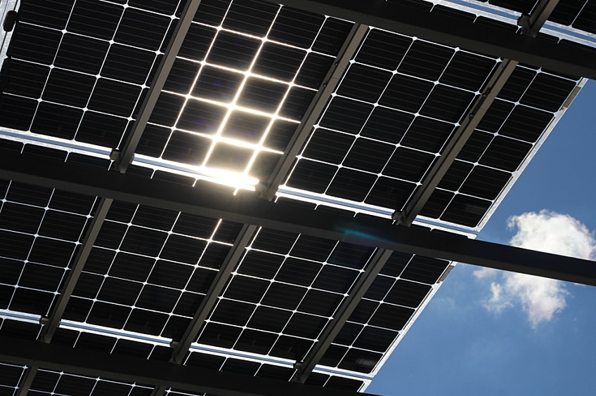
Bifacial solar panels do away with a reflective continuous metal back film and demand a more sophisticated cell design to ensure that the electrical energy is harvested efficiently. They are able to absorb solar energy from both sides with the general concept being as shown here:

Bifacial panels are not equally efficient in each direction and the rear direction usually operates at about 75% of what is achieved from the front. Clearly, such panels should be installed above highly reflective surfaces, such as cool roof membranes, as shown here:

The overall efficiency of bifacial modules is dependent upon the amount of light that reaches the rear side. LG,* a manufacturer of bifacial solar panels, has modeled how much additional power one of their panels could produce depending on the surface underneath. The following graphic from LG suggests that a white membrane could increase power output by 26.9%.

Cool roof membranes are known as diffuse reflectors as compared to mirrors which are specular reflectors. The difference is shown here:

The diffuse reflectance from a roof membrane has the potential to illuminate the underside of a bifacial solar module and drive output up significantly.

In practice, these bifacial panels are easily identified by the absence of a plastic back layer which is replaced with a glass layer, as shown in this example:

Source: Opsun Systems Inc.

There are many manufacturers of bifacial solar panels, including Canadian Solar, Jinko Solar, LG, LONGi, Sunpreme, Trina Solar, and Yingli Solar.* To enable light to enter from both sides, bifacial solar panels have glass on both faces, and therefore panel life may be longer. Additionally, bifacial panels can be produced without an aluminum frame, which may partly offset the cost of the extra sheet of glass.

As stated earlier, the output of bifacial solar panels is dependent on the reflectivity of the substrate. In the case of TPO single-ply roofing membranes, there are generally only minor differences between TPO membranes from different manufacturers in terms of initial reflectance. The critical measure is solar reflectance since it is visible light that provides energy for conversion to electricity. Solar Reflectance Index, or SRI, is not appropriate because it includes an emittance term which is a measure of heat being radiated from the surface.

The independent Cool Roof Rating Council shows GAF EverGuard® TPO to have an initial reflectivity of 0.76, in line with other standard TPO membranes. The three-year aged reflectivity is shown as 0.68, again in line with other TPO membranes. However, GAF EverGuard Extreme® has an initial reflectivity of 0.83, i.e., 7 percentage points higher than the standard TPO. The three-year aged value is stated to be 0.72.

The three-year aged membrane values are frequently regarded as being representative of "long term" reflectivity. However, this relationship is based on standardized testing and does not take into account site-specific issues or differences between membrane types. Membrane dirt pick-up is determined by many factors including location, roof slope, and the chemistry of the membrane. Discussion of location is beyond the scope of this article, although it is likely that a roof in an industrialized area could get dirtier than a similar roof in a rural area. There is significant anecdotal evidence that single-ply roofs without standing water stay cleaner than those with poor drainage. Single-ply assemblies with tapered polyiso, enabling good drainage, likely stay cleaner longer than roofs with limited to no slope and poor drainage, all other things being equal.

In terms of single-ply membrane type, PVC contains liquid plasticizers that migrate to the surface, which may make the membrane feel slightly sticky. Depending on the exact formulation, PVC can become gray with dirt that does not readily wash off.

As compared to PVC, TPO membranes are unlikely to exhibit stickiness or tackiness. Long-term dirt retention of TPO membranes depends on the type of dirt (e.g., dust versus industrial contaminants) and the smoothness of the membrane surface. By accelerating the aging using the same UV exposure test as in the ASTM D6878 TPO Specification, it is possible to get an indication of changes in surface morphology. The following pictures, taken with a 100X microscope, show the surface of standard TPO compared to that of GAF EverGuard Extreme® after exposure to over four times the ASTM D6878 requirement.

The standard TPO developed a rougher surface compared to that of GAF EverGuard Extreme®, the latter formulated for outstanding UV and heat resistance. This would suggest that the dirt retention of GAF EverGuard Extreme® might be lower than standard TPO and therefore lead to higher output when used in conjunction with bifacial solar panels. It is worth noting that the D6878 specification calls for an inspection of the surface with a 7X eyepiece, while the pictures above were taken using 100X magnification.

At the GAF Cedar City, Utah, facility, EverGuard Extreme® membrane has been installed on a lower roof in front of the building. As shown in the following photographs taken at mid-day during the summer over the past five years, the amount of reflection up onto the adjacent wall is still visibly noticeable.

The pictures help demonstrate the sun's energy that would be available via reflection to bifacial solar panels had any been installed. As noted by NREL, shown in the following figure, there are many variables to be considered when mounting bifacial solar panels:

However, given that annual power output gains of around 30 'Äì 35% have been demonstrated when bifacial solar panels were installed over substrates with a solar reflectance of 0.5 'Äì 0.6, then a membrane such as GAF EverGuard Extreme®, with a potential to maintain high reflectance over a long time period, could provide a major advantage.

In summary, bifacial solar panels can potentially increase the output relative to a traditional solar array by upwards of 30%. It makes sense to protect those gains over the long term by choosing a membrane designed for long life and that has the potential to better resist dirt retention during that time. The right choice of membrane is important for any solar installation, but for bifacial panels it becomes even more so.


*Trade and company names or company products referred to herein are intended only to describe the materials and products discussed. In no case do these references imply recommendation or endorsement, nor does it imply that the particular products are the best available for the purpose discussed.

About the Author

Thomas J Taylor, PhD is the Building & Roofing Science Advisor for GAF. Tom has over 20 year’s experience in the building products industry, all working for manufacturing organizations. He received his PhD in chemistry from the University of Salford, England, and holds approximately 35 patents. Tom’s main focus at GAF is roofing system design and building energy use reduction. Under Tom’s guidance GAF has developed TPO with unmatched weathering resistance.

Related Articles

Flat roof with hot air welded pvc membrane waterproofing for ballasted system
Building Science

Thermal Bridging Through Roof Fasteners: Why the Industry Should Take Note

What is going on here?No, this roof does not have measles, it has a problem with thermal bridging through the roof fasteners holding its components in place, and this problem is not one to be ignored.As building construction evolves, you'd think these tiny breaches through the insulating layers of the assembly, known as point thermal bridges, would matter less and less. But, as it happens, the reverse is true! The tighter and better-insulated a building, the bigger the difference all of the weak points, in its thermal enclosure, make. A range of codes and standards are beginning to address this problem, though it's important to note that there is often a time lag between development of codes and their widespread adoption.What Is the Industry Doing About It?Long in the business of supporting high-performance building enclosures, Phius (Passive House Institute US) provides a Fastener Correction Calculator along with a way to calculate the effect of linear thermal bridges (think shelf angles, lintels, and so on). By contrast, the 2021 International Energy Conservation Code also addresses thermal bridging, but only considers framing materials to be thermal bridges, and actually pointedly ignores the effects of point loads like fasteners in its definition of continuous insulation: "insulation material that is continuous across all structural members without thermal bridges other than fasteners and service openings" (Section C202). Likewise, The National Energy Code of Canada for Buildings: 2020 addresses thermal bridging of a number of building components, but also explicitly excludes fasteners: "in calculating the overall thermal transmittance of assemblies…fasteners need not be taken into account" (Section 3.1.1.7.3). Admittedly, point thermal bridges are often excluded because it is challenging to assess them with simple simulation tools.Despite this, researchers have had a hunch for decades that thermal bridging through the multitude of fasteners often used in roofs is in fact significant enough to warrant study. Investigators at the National Bureau of Standards, Oak Ridge National Laboratory, the National Research Council Canada, and consulting firms Morrison Hershfield and Simpson Gumpertz & Heger (SGH), have conducted laboratory and computer simulation studies to analyze the effects of point thermal bridges.Why Pay Attention Now?The problem has been made worse in recent years because changes in wind speeds, design wind pressures, and roof zones as dictated by ASCE 7-16 and 7-22 (see blogs by Jim Kirby and Kristin Westover for more insight), mean that fastener patterns are becoming denser in many cases. This means that there is more metal on average, per square foot of roof, than ever before. More metal means that more heat escapes the building in winter and enters the building in summer. By making our buildings more robust against wind uplift to meet updated standards, we are in effect making them less robust against the negative effects of hot and cold weather conditions.So, how bad is this problem, and what's a roof designer to do about it? A team of researchers at SGH, Virginia Tech, and GAF set out to determine the answer, first by simplifying the problem. Our plan was to develop computer simulations to accurately anticipate the thermal bridging effects of fasteners based on their characteristics and the characteristics of the roof assemblies in which they are used. In other words, we broke the problem down into parts, so we could know how each part affects the problem as a whole. We also wanted to carefully check the assumptions underlying our computer simulation and ensure that our results matched up with what we were finding in the lab. The full paper describing our work was delivered at the 2023 IIBEC Convention and Trade Show, but here are the high points, starting with how we set up the study.First, we began with a simple 4" polyisocyanurate board (ISO), and called it Case A-I.Next, we added a high-density polyisocyanurate cover board (HD ISO), and called that Case A-II.Third, we added galvanized steel deck to the 4" polyiso, and called that Case A-III.Finally, we created the whole sandwich: HD ISO and ISO over steel deck, which was Case A-IV.Note that we did not include a roof membrane, substrate board, air barrier, or vapor retarder in these assemblies, partly to keep it simple, and partly because these components don't typically add much insulation value to a roof assembly.The cases can be considered base cases, as they do not yet contain a fastener. We needed to simulate and physically test these, so we could understand the effect that fasteners have when added to them.We also ran a set of samples, B-I through B-IV, that corresponded with cases A-I through A-IV above, but had one #12 fastener, 6" long, in the center of the 2' x 2' assembly, with a 3" diameter insulation plate. These are depicted below. The fastener penetrated the ISO and steel deck, but not the HD ISO.One visualization of the computer simulation is shown here, for Case B-IV. The stripes of color, or isotherms, show the vulnerability of the assembly at the location of the fastener.What did we find? The results might surprise you.First, it's no surprise that the fastener reduced the R-value of the 2' x 2' sample of ISO alone by 4.2% in the physical sample, and 3.4% in the computer simulation (Case B-I compared to Case A-I).When the HD ISO was added (Cases II), R-value fell by 2.2% and 2.7% for the physical experiment and computer simulation, respectively, when the fastener was added. In other words, adding the fastener still caused a drop in R-value, but that drop was considerably less than when no cover board was used. This proved what we suspected, that the HD ISO had an important protective effect against the thermal bridging caused by the fastener.Next, we found that the steel deck made a big difference as well. In the physical experiment, the air contained in the flutes of the steel deck added to the R-value of the assembly, while the computer simulation did not account for this effect. That's an item that needs to be addressed in the next phase of research. Despite this anomaly, both approaches showed the same thing: steel deck acts like a radiator, exacerbating the effect of the fastener. In the assemblies with just ISO and steel deck (Cases III), adding a fastener resulted in an R-value drop of 11.0% for the physical experiment and 4.6% for the computer simulation compared to the assembly with no fastener.Finally, the assemblies with all the components (HD ISO, ISO and steel deck, a.k.a. Cases IV) showed again that the HD ISO insulated the fastener and reduced its negative impact on the R-value of the overall assembly. The physical experiment had a 6.1% drop (down from 11% with no cover board!) and the computer simulation a 4.2% drop (down from 4.6% with no cover board) in R-value when the fastener was added.What Does This Study Tell Us?The morals of the study just described are these:Roof fasteners have a measurable impact on the R-value of roof insulation.High-density polyisocyanurate cover boards go a long way toward minimizing the thermal impacts of roof fasteners.Steel deck, due to its high conductivity, acts as a radiator, amplifying the thermal bridging effect of fasteners.What Should We Do About It?As for figuring out what to do about it, this study and others first need to be extended to the real world, and that means making assumptions about parameters like the siting of the building, the roof fastener densities required, and the roof assembly type.Several groups have made this leap from looking at point thermal bridges to what they mean for a roof's overall performance. The following example was explored in a paper by Taylor, Willits, Hartwig and Kirby, presented at the RCI, Inc. Building Envelope Technology Symposium in 2018. In that paper, the authors extended computer simulation results from a 2015 paper by Olson, Saldanha, and Hsu to a set of actual roofing scenarios. They found that the installation method has a big impact on the in-service R-value of the roof.They assumed a 15,000-square-foot roof, fastener patterns and densities based on a wind uplift requirement of 120 pounds per square foot, and a design R-value of R-30. In this example, a traditional mechanically attached roof had an in-service R-value of only R-25, which is a 17% loss compared to the design R-value.An induction-welded roof was a slight improvement over the mechanically attached assembly, with an in-service value of only R-26.5 (a 12% loss compared to the design R-value).Adhering instead of fastening the top layer of polyiso resulted in an in-service R-value of R-28.7 (a 4% loss compared to the design R-value).Finally, in their study, an HD polyiso board was used as a mechanically fastened substrate board on top of the steel deck, allowing both layers of continuous polyiso insulation and the roof membrane to be adhered. Doing so resulted in an in-service R-value of R-29.5, representing only a 1.5% loss compared to the design R-value.To operationalize these findings in your own roofing design projects, consider the following approaches:Consider eliminating roof fasteners altogether, or burying them beneath one or more layers of insulation. Multiple studies have shown that placing fastener heads and plates beneath a cover board, or, better yet, beneath one or two layers of staggered insulation, such as GAF's EnergyGuard™ Polyiso Insulation, can dampen the thermal bridging effects of fasteners. Adhering all or some of the layers of a roof assembly minimizes unwanted thermal outcomes.Consider using an insulating cover board, such as GAF's EnergyGuard™ HD or EnergyGuard™ HD Plus Polyiso cover board. Installing an adhered cover board in general is good roofing practice for a host of reasons: they provide enhanced longevity and system performance by protecting roof membranes and insulation from hail damage; they allow for enhanced wind uplift and improved aesthetics; and they offer additional R-value and mitigate thermal bridging as shown in our recent study.Consider using an induction-welded system that minimizes the number of total roof fasteners by dictating an even spacing of insulation fasteners. The special plates of these fasteners are then welded to the underside of the roof membrane using an induction heat tool. This process eliminates the need for additional membrane fasteners.Consider beefing up the R-value of the roof insulation. If fasteners diminish the actual thermal performance of roof insulation, building owners are not getting the benefit of the design R-value. Extra insulation beyond the code minimum can be specified to make up the difference.Where Do We Go From Here?Some work remains to be done before we have a computer simulation that more closely aligns with physical experiments on identical assemblies. But, the two methods in our recent study aligned within a range of 0.8 to 6.7%, which indicates that we are making progress. With ever-better modeling methods, designers should soon be able to predict the impact of fasteners rather than ignoring it and hoping for the best.Once we, as a roofing industry, have these detailed computer simulation tools in place, we can include the findings from these tools in codes and standards. These can be used by those who don't have the time or resources to model roof assemblies using a lab or sophisticated modeling software. With easy-to-use resources quantifying thermal bridging through roof fasteners, roof designers will no longer be putting building owners at risk of wasting energy, or, even worse, of experiencing condensation problems due to under-insulated roof assemblies. Designers will have a much better picture of exactly what the building owner is getting when they specify a roof that includes fasteners, and which of the measures detailed above they might take into consideration to avoid any negative consequences.This research discussed in this blog was conducted with a grant from the RCI-IIBEC Foundation and was presented at IIBEC's 2023 Annual Trade Show and Convention in Houston on March 6. Contact IIBEC at https://iibec.org/ or GAF at BuildingScience@GAF.com for more information.

By Authors Elizabeth Grant

November 17, 2023

Rolling out cooling GAF Streetbond® coating in blue and white, Pacoima, L.A.
In Your Community

Creating Net-Positive Communities: GAF Taking Action to Drive Carbon Reduction

Companies, organizations, and firms working in the building, construction, and design space have a unique opportunity and responsibility. Collectively, we are contributing to nearly 40% of energy-related carbon emissions worldwide. While the goals, commitments, pledges, and promises around these challenges are a step in the right direction, no one entity alone will make major improvements to this daunting issue.We need to come together, demonstrate courageous change leadership, and take collective approaches to address the built environment's impacts on climate. Collectively, we have a unique opportunity to improve people's lives and make positive, measurable changes to impact:Buildings, homes, and hardscapesCommunity planningConsumer, commercial, and public sector behaviorOur Collective Challenge to Reduce our Carbon FootprintAccording to many sources, including the U.S. Green Building Council (USGBC), the built environment accounts for 39% of global energy-related carbon emissions worldwide. Operational emissions from buildings make up 28% and the remaining 11% comes from materials and construction.By definition, embodied carbon is emitted by the manufacture, transport, and installation of construction materials, and operational carbon typically results from heating, cooling, electrical use, and waste disposal of a building. Embodied carbon emissions are set during construction. This 11% of carbon attributed to the building materials and construction sector is something each company could impact individually based on manufacturing processes and material selection.The more significant 28% of carbon emissions from the built environment is produced through the daily operations of buildings. This is a dynamic that no company can influence alone. Improving the energy performance of existing and new buildings is a must, as it accounts for between 60–80% of greenhouse gas emissions from the building and construction sector. Improving energy sources for buildings, and increasing energy efficiency in the buildings' envelope and operating systems are all necessary for future carbon and economic performance.Why It Is Imperative to Reduce our Carbon Emissions TodayThere are numerous collectives that are driving awareness, understanding, and action at the governmental and organizational levels, largely inspired by the Paris Agreement enacted at the United Nations Climate Change Conference of Parties (COP21) in 2015. The Architecture 2030 Challenge was inspired by the Paris Agreement and seeks to reduce climate impacts from carbon in the built environment.Since the enactment of the Paris Agreement and Architecture 2030 Challenge, myopic approaches to addressing carbon have prevailed, including the rampant net-zero carbon goals for individual companies, firms, and building projects. Though these efforts are admirable, many lack real roadmaps to achieve these goals. In light of this, the US Security and Exchange Commission has issued requirements for companies, firms, and others to divulge plans to meet these lofty goals and ultimately report to the government on progress in reaching targets. These individual actions will only take us so far.Additionally, the regulatory environment continues to evolve and drive change. If we consider the legislative activity in Europe, which frequently leads the way for the rest of the world, we can all expect carbon taxes to become the standard. There are currently 15 proposed bills that would implement a price on carbon dioxide emissions. Several states have introduced carbon pricing schemes that cover emissions within their territory, including California, Oregon, Washington, Hawaii, Pennsylvania, and Massachusetts. Currently, these schemes primarily rely on cap and trade programs within the power sector. It is not a matter of if but when carbon taxes will become a reality in the US.Theory of ChangeClimate issues are immediate and immense. Our industry is so interdependent that we can't have one sector delivering amazing results while another is idle. Making changes and improvements requires an effort bigger than any one organization could manage. Working together, we can share resources and ideas in new ways. We can create advantages and efficiencies in shared R&D, supply chain, manufacturing, transportation, design, installation, and more.Collaboration will bring measurable near-term positive change that would enable buildings and homes to become net-positive beacons for their surrounding communities. We can create a network where each building/home has a positive multiplier effect. The network is then compounded by linking to other elements that contribute to a community's overall carbon footprint.Proof of Concept: GAF Cool Community ProjectAn estimated 85% of Americans, around 280 million people, live in metropolitan areas. As the climate continues to change, many urban areas are experiencing extreme heat or a "heat island effect." Not only is excess heat uncomfortable, but heat islands are public health and economic concerns, especially for vulnerable communities that are often most impacted.Pacoima, a neighborhood in Los Angeles, was selected by a consortium of partners as a key community to develop a first-of-its-kind community-wide research initiative to understand the impacts various cooling solutions have on urban heat and livability. Pacoima is a lower income community in one of the hottest areas in the greater Los Angeles area. The neighborhood represents other communities that are disproportionately impacted by climate change and often underinvested in.Implementation:Phase 1: This included the application of GAF StreetBond® DuraShield cool, solar-reflective pavement coatings on all ground-level hard surfaces, including neighborhood streets, crosswalks, basketball courts, parking lots, and playgrounds. The project also includes a robust community engagement process to support local involvement in the project, measure qualitative and quantitative impact on how cooling improves living conditions, and ensure the success of the project.Phase 2: After 12 months of monitoring and research, GAF and partners will evaluate the impact of the cool pavements with the intent to scale the plan to include reflective roofing and solar solutions.This ongoing project will allow us to evaluate for proof of concept and assess a variety of solutions as well as how different interventions can work together effectively (i.e., increasing tree canopies, greenspacing, cool pavements, cool roofs, etc.). Through community-wide approaches such as this, it's possible that we could get ahead of the legislation and make significant innovative contributions to communities locally, nationally, and globally.GAF Is Taking Action to Create Community-wide Climate SolutionsWith collaboration from leaders across the building space and adjacent sectors, we believe it is possible to drive a priority shift from net neutral to net positive. Addressing both embodied and operational carbon can help build real-world, net-positive communities.We invite all who are able and interested in working together in the following ways:Join a consortium of individuals, organizations, and companies to identify and develop opportunities and solutions for collective action in the built environment. The group will answer questions about how to improve the carbon impacts of the existing and future built environment through scalable, practical, and nimble approaches. Solutions could range from unique design concepts to materials, applications, testing, and measurement so we can operationalize solutions across the built environment.Help to scale the Cool Community project that was started in Pacoima. This can be done by joining in with a collaborative and collective approach to climate adaptation for Phase 2 in Pacoima and other cities around the country where similar work is beginning.Collaborate in designing and building scientific approaches to determine effective carbon avoidance—or reduction—efforts that are scalable to create net-positive carbon communities. Explore efforts to use climate adaptation and community cooling approaches (i.e., design solutions, roofing and pavement solutions, improved building envelope technologies, green spacing, tree coverage, and shading opportunities) to increase albedo of hard surfaces. Improve energy efficiency to existing buildings and homes and ultimately reduce carbon at the community level.To learn more and to engage in any of these efforts, please reach out to us at sustainability@gaf.com.

By Authors Jennifer Keegan

May 31, 2023

GAF Building and Roofing Science Team
Building Science

Developing Best Practice Solutions for GAF and Siplast Customers

With any roofing project, there are a number of factors to consider when choosing the right design: sustainability profile, potential risks, overall performance, and more. Our Building and Roofing Science (BRS) team specializes in working with industry professionals to help them enhance their roof designs across all of these areas. Leveraging their building enclosure expertise, our BRS team serves as thought leaders and collaborators, helping design professionals deliver better solutions for their customers."We're a consultant's consultant. Basically, we're a sounding board for them," explains Jennifer Keegan, Director of Building and Roofing Science. Rather than solely providing product specifications and tactical support, the BRS team partners with consultants, specifiers, and architects to provide guidance on designing high-performing roofs that don't just meet code, but evolve their practices and thinking. For example, this might include understanding the science behind properly placed air and vapor retarders.As experts in the field, our BRS team members frequently attend conferences to share their expertise and findings. As Jennifer explains, "Our biggest goal is to help designers make an informed decision." Those decisions might be in a number of areas, including the building science behind roof attachment options, proper placement of air and vapor retarders, and how a roof can contribute to energy efficiency goals.Expanding the BRS TeamOur BRS team is accessible nationwide to look at the overall science of roof assembly and all of the components and best practices that make up a high-performance, low-risk, and energy-efficient roof. Our regional experts are positioned strategically to better serve our customers and the industry as a whole. We have the capacity to work with partners across the country on a more personalized level, providing guidance on roof assembly, membrane type, attachment method, or complicated roof details including consideration of the roof to wall interface.Partnering with the Design Services TeamIn addition to our newly expanded BRS team, GAF also offers support through its Design Services team. This group helps with traditional applications, installations, and system approvals. GAF's Design Services team is a great resource to answer any product questions, help you ensure your project meets applicable code requirements, assess compatibility of products, outline specifications, and assist with wind calculations. By serving as the front line in partnership with our BRS team, the Design Services team can help guide the design community through any phase of a project.GAF's Building and Roofing Science team is the next step for some of those trickier building projects, and can take into consideration air, vapor, and thermal requirements that a designer might be considering for their roof assembly. Through a collaborative process, our BRS team seeks to inspire project teams, as Jennifer explains, "to do it the best way possible."Engaging with the TeamsGAF has the support you need for any of your design and roofing science needs. To request support from the GAF Design Services team, you can email designservices@gaf.com. For additional support from our Building and Roofing Science team regarding specialty installations or how a building can be supported by enhanced roof design, contact us at buildingscience@gaf.com.Our Building and Roofing Science team is always happy to support you as you work through complex jobs. You can also sign up to join their office hours here.

By Authors GAF Roof Views

May 08, 2023

Don't miss another GAF RoofViews post!

Subscribe now