RoofViews

Building Science

How to Choose the Best Membrane for a Commercial Solar Power Installation

By Thomas J Taylor

February 29, 2016

Solar installation on a commercial roof

At the end of 2014, there were 16,000 megawatts (MW) of installed solar power capacity in the U.S. Of that, around 4,750 MW were from commercial PV installations, which include low-slope rooftop installations (the remaining was from residential and utility installations). There is little doubt that solar power has become significant; in comparison, coal-fired power plants typically are between 400 to 600 MW each. Also, because efficiency is a factor, the most efficient U.S. coal-fired plant is right around 40% (the John W. Turk Plant in Arkansas).

Looking at past trends of solar installations as shown in the chart below, it's clear that we can expect continued rapid growth and falling solar costs that will help grow and expand the solar market.

chart

Although it varies depending on local circumstances, overall today, the cost of solar power has become competitive with traditional generation.

So, how do our roofing membrane choices play into this? There are several things to consider when selecting a membrane for a roof that might have a solar installation added.

Ease of Installation

Typical single-ply roofs have even surfaces that can be easily marked off and worked on during a solar installation. Wide and long sheets mean there are fewer seams and smooth surfaces mean that installers can rapidly get attachments and flashings installed.

Long-Term Roof Performance

No one wants to have to repair a roof that has a large solar array overburden. However, if the membrane is a multi-ply system, the job of even finding a leak gets exponentially harder. Solar arrays can't be "moved out of the way"—they are permanent and restrict access to the membrane. This again points to why single-ply membranes are the best choice.

However, membrane choice also comes down to the expected lifetime of the array versus that of the roof. Many studies have shown that solar arrays could be producing power well beyond 25 years. That makes it important to select a supplier and membrane type that can offer confidence in weathering resistance. EverGuard Extreme® is a good example of a membrane designed for long-term weather resistance, backed by an industry-leading warranty.

Solar Array Efficiency

The temperature of solar panels is a significant factor affecting how much electricity the panels produce. This is generally measured by the "temperature coefficient" of the solar panels, which is the percentage loss in efficiency per degree rise in temperature. So, as panels get hotter, they produce less power.

As listed on solar panel spec sheets, the power efficiency of an average panel is 16.21% at 111.2°F (45°C) and the "maximum power temperature coefficient" is -0.42% per °C. This means that the panel would lose 0.42% of its power output for every 1°C rise in rooftop temperature above 45°C (111.2°F). So, let's take a look at what that means for some typical roofs:

The GAF EverGuard Extreme® TPO membrane was designed to substantially reduce rooftop temperature. For instance, on a sunny day with an ambient air temperature of 89°F (32°C), the roof temperature measured on an EPDM, dark roof was 173°F (78°C), resulting in a 13.86% decrease in energy efficiency from the standard system; the roof temperature measured on an EverGuard Extreme® TPO roof was only 116°F (46.6°C), resulting in a decrease of only 0.67% in energy efficiency.

Of course, this is approximate because the air temperature around the panels might be slightly lower. However, it's clear that reflective membranes can result in more power output from solar arrays. This has actually been demonstrated in independent tests. So, typically we would expect the efficiency of a solar array to be about 13% higher when installed over a highly reflective membrane such as EverGuard Extreme® TPO, compared to a dark membrane with low reflectance.

Long-Term Membrane Reflectance

The reflectivity of a rooftop membrane is established through certifications by institutions such as the Cool Roof Rating Council (CRRC) or the ENERGY STAR® rating program administered by the Department of Energy and the Environmental Protection Agency. CRRC publishes searchable radiative data online. The reflectivity (Total Solar Reflectance or TSR) is the fraction of sunlight that a surface reflects and is measured on a scale of 0 to 1 (for example, a surface that reflects 55% of sunlight has a total solar reflectance of 0.55). According to the CRRC, the initial TSR for a typical dark EPDM membrane is a paltry 0.06 (or 3-year aged TSR of 0.07), while the TSR for the EverGuard Extreme® TPO roof is 0.835 (or 3-year aged TSR of 0.73)!

The following is a picture of a TPO roof with a solar array in New Jersey installed over 5 years ago.

solar1

The roof has never been cleaned, as can be seen by the dirt under the panels. But, where the membrane is fully exposed, rain has kept the membrane white and reflective. Clearly, based on their reflectivity, ease of maintenance, and longevity, white TPO membranes are the best choice for these applications.


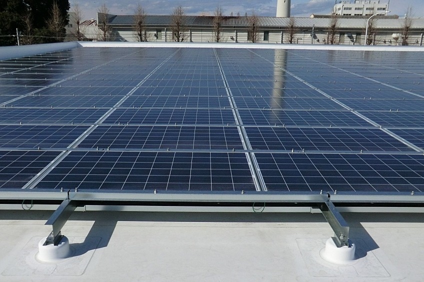
Lead photo credit: Sanko Fukaya Factory Administrative Office

About the Author

Thomas J Taylor, PhD is the Building & Roofing Science Advisor for GAF. Tom has over 20 year’s experience in the building products industry, all working for manufacturing organizations. He received his PhD in chemistry from the University of Salford, England, and holds approximately 35 patents. Tom’s main focus at GAF is roofing system design and building energy use reduction. Under Tom’s guidance GAF has developed TPO with unmatched weathering resistance.

Related Articles

Flat roof with hot air welded pvc membrane waterproofing for ballasted system
Building Science

Thermal Bridging Through Roof Fasteners: Why the Industry Should Take Note

What is going on here?No, this roof does not have measles, it has a problem with thermal bridging through the roof fasteners holding its components in place, and this problem is not one to be ignored.As building construction evolves, you'd think these tiny breaches through the insulating layers of the assembly, known as point thermal bridges, would matter less and less. But, as it happens, the reverse is true! The tighter and better-insulated a building, the bigger the difference all of the weak points, in its thermal enclosure, make. A range of codes and standards are beginning to address this problem, though it's important to note that there is often a time lag between development of codes and their widespread adoption.What Is the Industry Doing About It?Long in the business of supporting high-performance building enclosures, Phius (Passive House Institute US) provides a Fastener Correction Calculator along with a way to calculate the effect of linear thermal bridges (think shelf angles, lintels, and so on). By contrast, the 2021 International Energy Conservation Code also addresses thermal bridging, but only considers framing materials to be thermal bridges, and actually pointedly ignores the effects of point loads like fasteners in its definition of continuous insulation: "insulation material that is continuous across all structural members without thermal bridges other than fasteners and service openings" (Section C202). Likewise, The National Energy Code of Canada for Buildings: 2020 addresses thermal bridging of a number of building components, but also explicitly excludes fasteners: "in calculating the overall thermal transmittance of assemblies…fasteners need not be taken into account" (Section 3.1.1.7.3). Admittedly, point thermal bridges are often excluded because it is challenging to assess them with simple simulation tools.Despite this, researchers have had a hunch for decades that thermal bridging through the multitude of fasteners often used in roofs is in fact significant enough to warrant study. Investigators at the National Bureau of Standards, Oak Ridge National Laboratory, the National Research Council Canada, and consulting firms Morrison Hershfield and Simpson Gumpertz & Heger (SGH), have conducted laboratory and computer simulation studies to analyze the effects of point thermal bridges.Why Pay Attention Now?The problem has been made worse in recent years because changes in wind speeds, design wind pressures, and roof zones as dictated by ASCE 7-16 and 7-22 (see blogs by Jim Kirby and Kristin Westover for more insight), mean that fastener patterns are becoming denser in many cases. This means that there is more metal on average, per square foot of roof, than ever before. More metal means that more heat escapes the building in winter and enters the building in summer. By making our buildings more robust against wind uplift to meet updated standards, we are in effect making them less robust against the negative effects of hot and cold weather conditions.So, how bad is this problem, and what's a roof designer to do about it? A team of researchers at SGH, Virginia Tech, and GAF set out to determine the answer, first by simplifying the problem. Our plan was to develop computer simulations to accurately anticipate the thermal bridging effects of fasteners based on their characteristics and the characteristics of the roof assemblies in which they are used. In other words, we broke the problem down into parts, so we could know how each part affects the problem as a whole. We also wanted to carefully check the assumptions underlying our computer simulation and ensure that our results matched up with what we were finding in the lab. The full paper describing our work was delivered at the 2023 IIBEC Convention and Trade Show, but here are the high points, starting with how we set up the study.First, we began with a simple 4" polyisocyanurate board (ISO), and called it Case A-I.Next, we added a high-density polyisocyanurate cover board (HD ISO), and called that Case A-II.Third, we added galvanized steel deck to the 4" polyiso, and called that Case A-III.Finally, we created the whole sandwich: HD ISO and ISO over steel deck, which was Case A-IV.Note that we did not include a roof membrane, substrate board, air barrier, or vapor retarder in these assemblies, partly to keep it simple, and partly because these components don't typically add much insulation value to a roof assembly.The cases can be considered base cases, as they do not yet contain a fastener. We needed to simulate and physically test these, so we could understand the effect that fasteners have when added to them.We also ran a set of samples, B-I through B-IV, that corresponded with cases A-I through A-IV above, but had one #12 fastener, 6" long, in the center of the 2' x 2' assembly, with a 3" diameter insulation plate. These are depicted below. The fastener penetrated the ISO and steel deck, but not the HD ISO.One visualization of the computer simulation is shown here, for Case B-IV. The stripes of color, or isotherms, show the vulnerability of the assembly at the location of the fastener.What did we find? The results might surprise you.First, it's no surprise that the fastener reduced the R-value of the 2' x 2' sample of ISO alone by 4.2% in the physical sample, and 3.4% in the computer simulation (Case B-I compared to Case A-I).When the HD ISO was added (Cases II), R-value fell by 2.2% and 2.7% for the physical experiment and computer simulation, respectively, when the fastener was added. In other words, adding the fastener still caused a drop in R-value, but that drop was considerably less than when no cover board was used. This proved what we suspected, that the HD ISO had an important protective effect against the thermal bridging caused by the fastener.Next, we found that the steel deck made a big difference as well. In the physical experiment, the air contained in the flutes of the steel deck added to the R-value of the assembly, while the computer simulation did not account for this effect. That's an item that needs to be addressed in the next phase of research. Despite this anomaly, both approaches showed the same thing: steel deck acts like a radiator, exacerbating the effect of the fastener. In the assemblies with just ISO and steel deck (Cases III), adding a fastener resulted in an R-value drop of 11.0% for the physical experiment and 4.6% for the computer simulation compared to the assembly with no fastener.Finally, the assemblies with all the components (HD ISO, ISO and steel deck, a.k.a. Cases IV) showed again that the HD ISO insulated the fastener and reduced its negative impact on the R-value of the overall assembly. The physical experiment had a 6.1% drop (down from 11% with no cover board!) and the computer simulation a 4.2% drop (down from 4.6% with no cover board) in R-value when the fastener was added.What Does This Study Tell Us?The morals of the study just described are these:Roof fasteners have a measurable impact on the R-value of roof insulation.High-density polyisocyanurate cover boards go a long way toward minimizing the thermal impacts of roof fasteners.Steel deck, due to its high conductivity, acts as a radiator, amplifying the thermal bridging effect of fasteners.What Should We Do About It?As for figuring out what to do about it, this study and others first need to be extended to the real world, and that means making assumptions about parameters like the siting of the building, the roof fastener densities required, and the roof assembly type.Several groups have made this leap from looking at point thermal bridges to what they mean for a roof's overall performance. The following example was explored in a paper by Taylor, Willits, Hartwig and Kirby, presented at the RCI, Inc. Building Envelope Technology Symposium in 2018. In that paper, the authors extended computer simulation results from a 2015 paper by Olson, Saldanha, and Hsu to a set of actual roofing scenarios. They found that the installation method has a big impact on the in-service R-value of the roof.They assumed a 15,000-square-foot roof, fastener patterns and densities based on a wind uplift requirement of 120 pounds per square foot, and a design R-value of R-30. In this example, a traditional mechanically attached roof had an in-service R-value of only R-25, which is a 17% loss compared to the design R-value.An induction-welded roof was a slight improvement over the mechanically attached assembly, with an in-service value of only R-26.5 (a 12% loss compared to the design R-value).Adhering instead of fastening the top layer of polyiso resulted in an in-service R-value of R-28.7 (a 4% loss compared to the design R-value).Finally, in their study, an HD polyiso board was used as a mechanically fastened substrate board on top of the steel deck, allowing both layers of continuous polyiso insulation and the roof membrane to be adhered. Doing so resulted in an in-service R-value of R-29.5, representing only a 1.5% loss compared to the design R-value.To operationalize these findings in your own roofing design projects, consider the following approaches:Consider eliminating roof fasteners altogether, or burying them beneath one or more layers of insulation. Multiple studies have shown that placing fastener heads and plates beneath a cover board, or, better yet, beneath one or two layers of staggered insulation, such as GAF's EnergyGuard™ Polyiso Insulation, can dampen the thermal bridging effects of fasteners. Adhering all or some of the layers of a roof assembly minimizes unwanted thermal outcomes.Consider using an insulating cover board, such as GAF's EnergyGuard™ HD or EnergyGuard™ HD Plus Polyiso cover board. Installing an adhered cover board in general is good roofing practice for a host of reasons: they provide enhanced longevity and system performance by protecting roof membranes and insulation from hail damage; they allow for enhanced wind uplift and improved aesthetics; and they offer additional R-value and mitigate thermal bridging as shown in our recent study.Consider using an induction-welded system that minimizes the number of total roof fasteners by dictating an even spacing of insulation fasteners. The special plates of these fasteners are then welded to the underside of the roof membrane using an induction heat tool. This process eliminates the need for additional membrane fasteners.Consider beefing up the R-value of the roof insulation. If fasteners diminish the actual thermal performance of roof insulation, building owners are not getting the benefit of the design R-value. Extra insulation beyond the code minimum can be specified to make up the difference.Where Do We Go From Here?Some work remains to be done before we have a computer simulation that more closely aligns with physical experiments on identical assemblies. But, the two methods in our recent study aligned within a range of 0.8 to 6.7%, which indicates that we are making progress. With ever-better modeling methods, designers should soon be able to predict the impact of fasteners rather than ignoring it and hoping for the best.Once we, as a roofing industry, have these detailed computer simulation tools in place, we can include the findings from these tools in codes and standards. These can be used by those who don't have the time or resources to model roof assemblies using a lab or sophisticated modeling software. With easy-to-use resources quantifying thermal bridging through roof fasteners, roof designers will no longer be putting building owners at risk of wasting energy, or, even worse, of experiencing condensation problems due to under-insulated roof assemblies. Designers will have a much better picture of exactly what the building owner is getting when they specify a roof that includes fasteners, and which of the measures detailed above they might take into consideration to avoid any negative consequences.This research discussed in this blog was conducted with a grant from the RCI-IIBEC Foundation and was presented at IIBEC's 2023 Annual Trade Show and Convention in Houston on March 6. Contact IIBEC at https://iibec.org/ or GAF at BuildingScience@GAF.com for more information.

By Authors Elizabeth Grant

November 17, 2023

very severe hail
Building Science

Defending Against Very Severe Hail

Think that your roof doesn't need protection against hail? Think again.Severe hail events are increasing in geographic footprint and are no longer just in hail alley. The geographic region that experiences 1 inch or larger hailstones has expanded to be nearly two-thirds of the United States. Nearly 10 percent more U.S. properties, more than 6.8 million, were affected by hail in 2021 than in 2020. Coinciding with the increase in properties affected by a damaging hail event in 2021, there was also an increase in insurance claims, which rose to $16.5 billion from $14.2 billion in 2020.Figure 1: The estimated number of properties affected by one or more damaging hail events. Source: NOAA, graphed by VeriskAccording to data from Factory Mutual Insurance Company (FM Global), a leader in establishing best practices to protect buildings, the review of client losses between 2016-20, showed that the average wind/hail losses averaged $931,000 per event. That's a significant impact on a business, and it doesn't account for the other effects that a disruptive loss could have such as headaches from the process of repairing or replacing damaged roofs. As a result, designing the roof to withstand damage from hail events has become not only a best practice, but a necessity.Why does hail size matter?FM Approvals is a third-party testing and certification laboratory with a focus on testing products for property loss prevention using rigorous standards. FM Global, through the loss prevention data sheets, requires the use of FM Approved roof systems. FM Global estimates their clients lose about $130M each year on average from hail events in the United States. Given the increasing volume of severe hail events and the resulting property loss, damage, and financial impacts, FM Global added to the requirements in the FM Loss Prevention Data Sheet (LPDS) 1-34 Hail Damage in 2018. Loss Prevention Data Sheets provide FM's best advice for new construction and for Data Sheet 1-34, this includes new or reroofing projects on existing buildings. Data Sheet 1-34 provides guidelines to minimize the potential for hail damage to buildings and roof-mounted equipment. FM Global intends that the data sheets apply to its insured buildings; however, some designers use data sheets as design guidelines for buildings other than those insured by FM Global.FM's LPDS 1-34 identifies the hail hazard areas across the United States: Moderate Hail hazard area, Severe Hail hazard area, and Very Severe Hail (VSH) hazard area which are defined by hail size. Note that the VSH area roughly correlates to Hail Alley. Hail Alley receives more hailstorms, and more severe ones, compared to other parts of the country.Figure 2: FM's LPDS 1-34 map outlining the different hail categories: moderate, severe, and very severe. The Very Severe area is most commonly referred to as "Hail alley".The hail hazard areas are divided by hail size, with the Very Severe hail hazard area being the largest hail size of greater than 2 inches. As a result, roofing assemblies have to meet the most stringent hail testing for designation in the Very Severe hazard area.Figure 3: Description of FM Approval hail regions.Even if you are not in hail alley, or one of the states in FM's Very Severe Hail area, hail larger than 2 inches still has the potential to occur throughout the contiguous United States. The National Oceanic and Atmospheric Administration (NOAA) tracks weather events throughout the United States, including hail. NOAA's hail database includes information such as location, date, and magnitude (size) of the hail stone for each event. A sampling of typical data is provided below; note that several states that are outside of FM's VSH zone, had hail events that would qualify as VSH, where hail stones were recorded to be larger than 2-inches in size.Figure 4: Hail events in states that are outside of the VSH area, but qualify as VSH by size.How Do I Design For Very Severe Hail?In order for a roof assembly to achieve a hail rating, the assembly must pass a hail test. FM Approvals designs the hail tests including a different test for each hail hazard area. Hail testing generally includes the use of steel or ice balls that are dropped or launched at roof assemblies in a laboratory setting. Pass criteria vary by the test, but generally visual damage cannot be present to either the membrane or components below. Roof assemblies that pass each individual hail test are FM approved to be installed in each hail hazard area.There are thousands of FM rated assemblies and it can be difficult to choose just one. To start, it is important to note that selection consists of an entire assembly, however consideration of all roof components including the membrane, coverboard, and attachment method each play an important role in how the assembly defends against hail.Membrane selection is critical for Very Severe Hail prone regions. Thicker roof membranes, as well as higher performance grades that will remain pliable under heat and UV exposure over time and will outperform standard grade materials. Fleeceback membranes also provide an added cushion layer that buffers hail impact.Coverboard selection is a critical component of the roof system design. High compressive strength coverboards are an effective means to enhance the performance of the roof system when exposed to hail events. A coverboard will enhance the roof's long term performance by fortifying the membrane when hail strikes as well as providing a firm surface to help resist damage from typical foot traffic. It will also help the roof insulation below withstand damage from hail. While conventional gypsum coverboards and high-density polyiso coverboards provide excellent protection against foot traffic and smaller hail, they are not effective for VSH. Coverboards for VSH systems were originally limited to plywood or oriented strand board (OSB). The use of plywood and OSB is very labor intensive to install as compared to traditional gypsum coverboards, increasing the cost of the installation. Recently, coverboard manufacturers have developed glass mat roof boards which are a reinforced gypsum core with a heavy-duty coated glass mat facer. Not only do these boards provide protection against 2-inch hail and are an important part of VSH assemblies, they are also a FM Class 1 and UL Class A thermal barrier for fire rated assemblies. These boards are 5/8" thick and are 92-96 pounds per 4'x8' board; about 30 percent heavier compared to plywood yet easier to install as they can be scored and cut like a traditional gypsum board.Consideration of roof attachment method is critical for selection of VSH assemblies. Historically, mechanically attached systems were not able to pass the VSH tests; when an ice ball hit the head of the fastener or plate, the result was a laceration in the membrane. To avoid failures of the membrane at the fasteners and plates, the fasteners were traditionally buried in the system; the insulation was mechanically attached and the coverboard and membrane were adhered. This is still a common installation method and as a result, there are a large number of assemblies where the membrane and coverboard are adhered. Additionally, burying the fasteners allows for the installation of a smooth backed membrane. With the development of glass mat coverboards, there are VSH rated assemblies that can be simultaneously fastened (mechanically attached coverboard and insulation) that utilize an adhered fleece-back membrane.Figure 5: VSH systems. Left is simultaneously fastened 60 mil Fleeceback TPO over glass mat VSH roof board and Polyiso Insulation. Right is 60 mil Fleeceback TPO over glass mat VSH roof board adhered in low rise foam ribbons to mechanically attached Polyiso Insulation.Figure 6: A sample of available VSH assemblies.SummaryWhy Should We Design for VSH?Severe hail events are increasing in geographic footprint and storms with hailstones that meet Very Severe Hail criteria are occurring throughout the country. While designing for VSH is a requirement if a building falls within the VSH area and is ensured by FM Global, many owners and designers are opting for roof assemblies that can withstand VSH storms even if they are not insured by FM Global. Material selection, such as coverboard and membrane, are key components to managing this risk. Glass mat coverboards and thicker, higher grade single-ply membranes, such as fleece-back, increase the roof assembly's resistance to damage. Choosing the right roof assembly could be the difference between weathering the storm or significant damage from hail.What are the next steps?Learn about GAF's Hail Storm System Resources, and as always, feel free to reach out to the Building & Roofing Science team with questions.

By Authors Kristin Westover

January 30, 2023

Roof design services team
Building Science

How Architects Can Lean on Roof Design Services for Project Success

Architects strive to achieve a roof design that will perform well and meet project-specific requirements. That often means incorporating the building code and warranty/guarantee requirements that building owners must meet — among the most important factors of any construction project — into the design. This isn't made any easier by the sheer number of roofing systems available. Even experienced architects can find it challenging to get familiar with all available components and identify which materials are going to be suitable for a particular building.Enter the GAF Design Services Team. Formed by merging together three different departments — field services, technical support services, and architectural information services — these technical professionals help support architects in delivering high-performing roofing systems that meet project-specific requirements.Support from Start to FinishAs GAF Senior Design Services Specialist Jesse Caruso explains, "The goal of Design Services is to essentially combine all three of those tasks into one large service team that assists architects, engineers, specifiers, consultants, sales reps, and contractors achieve their roof design goals. From the moment someone says they need a new roof, we are there throughout the entire process to provide support, all the way until the end of that roof guarantee."Each region of the country has dedicated Design Services personnel just a phone call away, ready to provide information about GAF commercial roofing systems. They understand the unique needs of different geographic areas of the country."We help walk a contractor or an owner or architect through that entire roofing lifecycle," says Caruso. "From how to install the system to what kind of warranty or guarantee you're going to get and how to maintain that guarantee or warranty."GAF's Port Arthur, TX Design Services Team: Dacia Belt, Nathan Vidrine, Shelby Noland, Brittany Castillo, Stephanie Lawrence, Melissa Vaughan, Traci Hicks, Jessica Crabtree, Traci Smith, Melanie Miller, Shelly Benoit, & Brittany SanchezSome of the topics Caruso's team is asked to assist with most frequently include:Product Testing: The Design Services team can confirm and provide documentation that shows which products and systems meet ASTM or UL standards for fire and hail resistance. They can also verify wind uplift ratings and other special approvals, such as Factory Mutual and Miami-Dade approvals.Installation Guidelines: The team can provide data on how different methods of installation can affect roofs' performance and guarantees. For instance, if a building is in a coastal area and needs a higher wind uplift rating, the team can provide guidance on fastening patterns and other installation strategies that will help meet that wind uplift requirement.Guarantee Terms: One of the most important aspects for building owners to consider is the warranty or guarantee protection provided by the roofing manufacturer. The Design Services team can assist by verifying what types of coverage are available and what contractor certifications are necessary to deliver a certain type of warranty or guarantee.Documentation: The team can provide professional documentation that supports product testing, ratings, and warranty/guarantee information. One submittal package may contain design lines, cut specs, system letters, data sheets, and more. This documentation can provide assurance from the manufacturer that the roof system will meet or exceed project requirements.An Architect's Partner for SuccessNo matter what challenges professionals may encounter while designing a new roofing system, the GAF Design Services Team is there to assist. You can be confident that the finished roofing system will provide the desired performance and protect the building for years to come.Reach out to the team by emailing designservices@gaf.com or visiting the design professionals help page.

By Authors Karen L Edwards

November 22, 2022

Don't miss another GAF RoofViews post!

Subscribe now