RoofViews

Building Science

Is your Cold Storage energy use through the roof?

By Kristin Westover

April 21, 2021

Cold storage facility for fresh produce

This piece is co-written by Jennifer Keegan, AAIA.


The headaches of Cold Storage facility operations extend beyond making sure the ice cream doesn't melt. Owners and Operators are regularly challenged with:

  • Selecting a cost-effective roof system that is going to be long-lasting
  • Working around unsafe areas in the interior due to ice accumulation
  • Struggling to reduce monthly energy bills

For Owners who are looking to increase energy savings and safety records, your roof not only keeps the weather out, but can help resolve these operational issues.

_____________

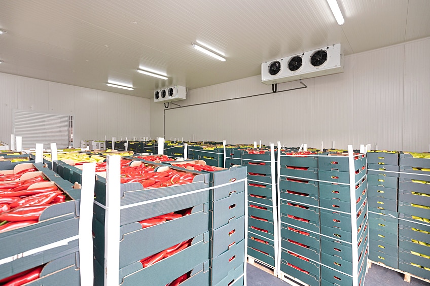
Cold Storage buildings are designed to maintain cold temperatures, much colder temperatures than a typical building. Cold storage facilities, such as blast freezers, may be required to maintain an interior temperature of minus 50 degrees Fahrenheit. Having a structure that is properly insulated and sealed to maintain the required temperature and minimize ice build-up is important not only for the products being stored inside, but also for potential energy savings over the life of the facility.

How can roofing materials impact energy savings?

Think of the walls of the Cold Storage facility as a jacket, and the roof as a hat. When it is cold outside, you want to make sure that you have a jacket and a hat to insulate and keep you warm. The same idea applies to a Cold Storage facility — the roof and walls of the structure insulate the products inside. But in this case, when it's warm outside, they keep the products inside cold. Not having enough insulation, on either the walls or the roof, will make your mechanical systems work harder to maintain the interior temperatures, which increases energy use, and can result in higher energy bills.

The effectiveness of roof insulation is determined by its R-value. According to Energy Star, R-value is a measure of an insulation's ability to resist heat traveling through it. The higher the R-value, the better the thermal performance of the insulation and its effectiveness at maintaining interior temperatures. R-value is typically expressed as a value per inch of insulation, and the recommended R-value of Cold Storage spaces will vary based on the interior temperature, although they are much higher than typically recommended for a traditional building. For comparison, a traditional office building may require an R-value of 30. In the 2018 edition of the American Society of Heating, Refrigeration and Air Conditioning Engineers' ASHRAE Handbook – Refrigeration, there are suggested minimum R-values for Roof Insulation between 30 and 60, depending on the cold storage type.

R-values will vary by product, including factors such as thickness and density. When calculating the total R-value of a multilayered installation, adding the R-values of the individual layers will provide the total R-value in the system. Particularly in Cold Storage, it makes sense to select an insulation that provides a higher R-value per inch, such as Polyisocyanurate (Polyiso, R-5.6 per inch), Extruded Polystyrene (XPS R-5.0 per inch), or Expanded Polystyrene (EPS R-3.8 per inch).

While insulations come in many thicknesses, it is a best practice to install several layers of thinner insulation rather than one or two layers of thicker insulation in order to reduce thermal bridging. Thermal bridging occurs when insulation is discontinuous between joints, allowing for air and thermal movement between the joints or gaps between boards. During installation, the use of several layers of insulation allows for staggering and offsetting the insulation joints, and blocks the passages that allow for air to bypass the insulation. Limiting thermal bridging can increase energy efficiency as it limits air movement between insulation boards.

Figure 1: Lower energy efficiency resulting from air movement between boards and fasteners acting as a thermal bridge.

Adding the adequate amount of insulation will prevent uncontrolled loss of the interior conditioned air, as well as assist in maintaining the required interior temperatures. Better maintaining the interior conditioned temperatures means that the cooling systems are required to run less often, which can equate to energy savings. While there may be an additional upfront cost to install an additional layer of insulation to increase the overall R-value of the roof, the cost should be minimal compared to the long-term savings of the added insulation. Of course, energy cost savings are not guaranteed and the amount of savings may vary based on climate zone, utility rates, radiative properties of roofing products, insulation levels, HVAC equipment efficiency and other factors.

What about the roof membrane? While there are many choices when it comes to the type of membrane, the most common discussion revolves around the color of the membrane. For a typical building, maintaining a comfortable space involves both heating and cooling, depending on the season. For the typical building, the color selection of the membrane has a greater effect when the interior of the building is being cooled. A highly reflective (light colored) roof membrane offers extra benefits when the interior is being cooled, because it will reflect heat from the sun. Similarly, for a Cold Storage building, it is beneficial to select a lighter-colored roof in order to reflect the heat from the sun to assist in reducing the already high costs related to cooling the building. Reflecting heat from the sun will decrease the heat radiating into the interior, which means the cooling equipment will not have to work as hard to maintain interior temperatures, and will ultimately work more efficiently.

What about roof attachment? We discussed the concept of thermal bridging and how energy loss occurs at discontinuities between the joints of the insulation, but thermal bridging can also occur where there are fastener penetrations through the roof system, as seen in Figure 1. Fasteners are used to attach the insulation and the membrane to the roof deck, which is referred to as a mechanically attached system. A way to reduce the thermal bridging that occurs at fastener penetrations is to bury them in the system or eliminate them altogether and install an adhered roof system. An adhered roof system typically fastens the bottom layer of insulation to the deck level and then subsequent layers of insulation, membrane and coverboard, are adhered. By eliminating the fasteners, the path for air to travel into the roof system is also reduced.

Figures 2 and 3 illustrate good and better scenarios, in terms of limiting thermal bridging and reducing air flow into the roof assembly. In Figure 2, labeled as the 'good' scenario, there are multiple layers of insulation, staggered and offset, but they are mechanically attached to the deck. While the staggered insulation layers limit some of the air flow into the roof assembly, air is still able to travel throughout the roof. In Figure 3, labeled as the 'better' scenario, only the first layer of insulation is mechanically attached and subsequent layers are adhered. By adhering the subsequent layers, air flow into the roof assembly is greatly reduced. Reducing air flow assists in maintaining interior temperatures, which can result in energy savings for the facility.

Figure 2: "Good Scenario" with staggered and offset insulation and a mechanically attached roof membrane.

Figure 3: "Better Scenario" with the first layer of insulation mechanically attached and subsequent layers of the roof system adhered, greatly reducing the air flow into the roof assembly.

The Devil is in the Details

The result of limiting air flow through the roof assembly of a Cold Storage facility is not a matter of occupant comfort, but a matter of occupant safety. In a traditional building, such as an office building, a poorly detailed roof termination could result in drafty offices or temperature complaints. In a Cold Storage facility, those same drafts condense due to the large temperature differential between the interior and exterior and the condensation can turn into ice. The ice can form on various surfaces including locations where air leakage is occurring, such as at roof-to-wall interfaces, but also on the Cold Storage floors where the surface of the floor is cooler than the air above it. When ice forms on the floors, it can cause slips, trips, or falls, and can also impact operations if a particular area of the facility has to be avoided.

Ice formation inside a Cold Storage facility is the result of improperly designed or executed details. Details, such as those at the wall-to-roof interface, or sealing around penetrations, are crucial to not only keep out rain, but to conserve energy within the facility. Similar to the loss of energy created by thermal bridging, air flow through the roof created by poor detailing results in considerable loss of the cooled temperatures required in the space below. Additionally, air flow that condenses can collect within the roof assembly, including within the insulation, and freeze. Frozen insulation is a common side effect of a Cold Storage roof that is not functioning properly. Frozen insulation is exactly what it sounds like — insulation that has had moisture accumulate within it and then freezes. Frozen insulation has properties similar to wet insulation and is ineffective, since it provides virtually no insulating properties. A frozen roof is almost like having no insulation at all, and the energy used to maintain the interior temperatures goes through the roof!

Proper detailing of a Cold Storage facility begins during the planning stage. Determining the type of interior spaces, the sizes, and the overall usage of the facility should be taken into consideration. Once the overall layout of the Cold Storage facility is decided, the construction materials, including the roof assembly, will need to be determined. Once the roof assembly is selected, design of the roof details is crucial. Typical details, including roof-to-wall interface and penetrations, must be meticulously thought out and designed.

Roof-to-wall interfaces and penetrations must be sealed to prevent air from entering into the roof assembly. Even the smallest gap that allows air flow can have detrimental effects on the roof assembly. The most common method of ensuring sealed terminations and penetrations is the use of a closed-cell spray foam. Closed-cell spray foam is typically installed at the intersection of the exterior walls and the roof insulation at a width of one inch and extends from the deck level to the top of the insulation. At wall-to-steel deck intersections, it is also best practice to install spray foam in the deck flutes a minimum of 12 inches from the wall. The closed cell spray foam helps to seal the interface so air cannot enter into the roof assembly.

Figure 4: GAF Detail 201C Coated Metal Roof Edge at Insulated Wall Panel

Proper execution of the roof installation is critical and requires a contractor with Cold Storage construction experience. Having the right partner who understands the importance of their role in the project and collaborates with the team can make or break the project. A future article will dive into these details. In the meantime, for information on GAF-certified contractors, talk to GAF first.

The benefits outweigh the risks. Seemingly insignificant decisions made during the design and construction of the roof of a Cold Storage facility can impact the functionality and energy usage of the building for the lifetime of the roof system, which is typically 25-35 years. Once air leakage occurs into a roof assembly, the damage that occurs is often irreversible. Ice accumulation on the floor can be a serious hazard for occupants and workers. The challenge of identifying where the breaches in the roof assembly occur, let alone remediation, can be difficult and costly. Remediation of the identified problems generally includes removal of frozen insulation as well as addressing the identified problem areas which are often attributed to detailing and air leakage. The associated consequence of a poorly designed and installed roof is the cost of the energy loss. Mechanical equipment having to work harder to maintain temperatures will result in higher costs due to an increase in energy use, and the effect of the equipment working harder often leads to premature mechanical failures. The benefits associated with designing and installing a proper Cold Storage roof far outweigh the risks. A properly designed and constructed roof will save energy, prolong the life of mechanical equipment, and protect both the building's occupants and the goods being stored inside the facility.

Need to talk to an expert regarding Cold Storage roof design? Talk to GAF first. Email us at coldstorage.assistance@gaf.com for design questions, detailing assistance, and expert advice.

About the Author

Kristin Westover, P.E., LEED AP O+M, is a Technical Manager of Specialty Installations for low-slope commercial roofing systems at GAF. She specializes in cold storage roofing assemblies where she provides insight, education, and best practices as it relates to cold storage roofing. Kristin is part of the Building and Roofing Science Team where she works with designers on all types of low-slope roofing projects to review project design considerations so designers can make informed roof assembly decisions.

Related Articles

Flat roof with hot air welded pvc membrane waterproofing for ballasted system
Building Science

Thermal Bridging Through Roof Fasteners: Why the Industry Should Take Note

What is going on here?No, this roof does not have measles, it has a problem with thermal bridging through the roof fasteners holding its components in place, and this problem is not one to be ignored.As building construction evolves, you'd think these tiny breaches through the insulating layers of the assembly, known as point thermal bridges, would matter less and less. But, as it happens, the reverse is true! The tighter and better-insulated a building, the bigger the difference all of the weak points, in its thermal enclosure, make. A range of codes and standards are beginning to address this problem, though it's important to note that there is often a time lag between development of codes and their widespread adoption.What Is the Industry Doing About It?Long in the business of supporting high-performance building enclosures, Phius (Passive House Institute US) provides a Fastener Correction Calculator along with a way to calculate the effect of linear thermal bridges (think shelf angles, lintels, and so on). By contrast, the 2021 International Energy Conservation Code also addresses thermal bridging, but only considers framing materials to be thermal bridges, and actually pointedly ignores the effects of point loads like fasteners in its definition of continuous insulation: "insulation material that is continuous across all structural members without thermal bridges other than fasteners and service openings" (Section C202). Likewise, The National Energy Code of Canada for Buildings: 2020 addresses thermal bridging of a number of building components, but also explicitly excludes fasteners: "in calculating the overall thermal transmittance of assemblies…fasteners need not be taken into account" (Section 3.1.1.7.3). Admittedly, point thermal bridges are often excluded because it is challenging to assess them with simple simulation tools.Despite this, researchers have had a hunch for decades that thermal bridging through the multitude of fasteners often used in roofs is in fact significant enough to warrant study. Investigators at the National Bureau of Standards, Oak Ridge National Laboratory, the National Research Council Canada, and consulting firms Morrison Hershfield and Simpson Gumpertz & Heger (SGH), have conducted laboratory and computer simulation studies to analyze the effects of point thermal bridges.Why Pay Attention Now?The problem has been made worse in recent years because changes in wind speeds, design wind pressures, and roof zones as dictated by ASCE 7-16 and 7-22 (see blogs by Jim Kirby and Kristin Westover for more insight), mean that fastener patterns are becoming denser in many cases. This means that there is more metal on average, per square foot of roof, than ever before. More metal means that more heat escapes the building in winter and enters the building in summer. By making our buildings more robust against wind uplift to meet updated standards, we are in effect making them less robust against the negative effects of hot and cold weather conditions.So, how bad is this problem, and what's a roof designer to do about it? A team of researchers at SGH, Virginia Tech, and GAF set out to determine the answer, first by simplifying the problem. Our plan was to develop computer simulations to accurately anticipate the thermal bridging effects of fasteners based on their characteristics and the characteristics of the roof assemblies in which they are used. In other words, we broke the problem down into parts, so we could know how each part affects the problem as a whole. We also wanted to carefully check the assumptions underlying our computer simulation and ensure that our results matched up with what we were finding in the lab. The full paper describing our work was delivered at the 2023 IIBEC Convention and Trade Show, but here are the high points, starting with how we set up the study.First, we began with a simple 4" polyisocyanurate board (ISO), and called it Case A-I.Next, we added a high-density polyisocyanurate cover board (HD ISO), and called that Case A-II.Third, we added galvanized steel deck to the 4" polyiso, and called that Case A-III.Finally, we created the whole sandwich: HD ISO and ISO over steel deck, which was Case A-IV.Note that we did not include a roof membrane, substrate board, air barrier, or vapor retarder in these assemblies, partly to keep it simple, and partly because these components don't typically add much insulation value to a roof assembly.The cases can be considered base cases, as they do not yet contain a fastener. We needed to simulate and physically test these, so we could understand the effect that fasteners have when added to them.We also ran a set of samples, B-I through B-IV, that corresponded with cases A-I through A-IV above, but had one #12 fastener, 6" long, in the center of the 2' x 2' assembly, with a 3" diameter insulation plate. These are depicted below. The fastener penetrated the ISO and steel deck, but not the HD ISO.One visualization of the computer simulation is shown here, for Case B-IV. The stripes of color, or isotherms, show the vulnerability of the assembly at the location of the fastener.What did we find? The results might surprise you.First, it's no surprise that the fastener reduced the R-value of the 2' x 2' sample of ISO alone by 4.2% in the physical sample, and 3.4% in the computer simulation (Case B-I compared to Case A-I).When the HD ISO was added (Cases II), R-value fell by 2.2% and 2.7% for the physical experiment and computer simulation, respectively, when the fastener was added. In other words, adding the fastener still caused a drop in R-value, but that drop was considerably less than when no cover board was used. This proved what we suspected, that the HD ISO had an important protective effect against the thermal bridging caused by the fastener.Next, we found that the steel deck made a big difference as well. In the physical experiment, the air contained in the flutes of the steel deck added to the R-value of the assembly, while the computer simulation did not account for this effect. That's an item that needs to be addressed in the next phase of research. Despite this anomaly, both approaches showed the same thing: steel deck acts like a radiator, exacerbating the effect of the fastener. In the assemblies with just ISO and steel deck (Cases III), adding a fastener resulted in an R-value drop of 11.0% for the physical experiment and 4.6% for the computer simulation compared to the assembly with no fastener.Finally, the assemblies with all the components (HD ISO, ISO and steel deck, a.k.a. Cases IV) showed again that the HD ISO insulated the fastener and reduced its negative impact on the R-value of the overall assembly. The physical experiment had a 6.1% drop (down from 11% with no cover board!) and the computer simulation a 4.2% drop (down from 4.6% with no cover board) in R-value when the fastener was added.What Does This Study Tell Us?The morals of the study just described are these:Roof fasteners have a measurable impact on the R-value of roof insulation.High-density polyisocyanurate cover boards go a long way toward minimizing the thermal impacts of roof fasteners.Steel deck, due to its high conductivity, acts as a radiator, amplifying the thermal bridging effect of fasteners.What Should We Do About It?As for figuring out what to do about it, this study and others first need to be extended to the real world, and that means making assumptions about parameters like the siting of the building, the roof fastener densities required, and the roof assembly type.Several groups have made this leap from looking at point thermal bridges to what they mean for a roof's overall performance. The following example was explored in a paper by Taylor, Willits, Hartwig and Kirby, presented at the RCI, Inc. Building Envelope Technology Symposium in 2018. In that paper, the authors extended computer simulation results from a 2015 paper by Olson, Saldanha, and Hsu to a set of actual roofing scenarios. They found that the installation method has a big impact on the in-service R-value of the roof.They assumed a 15,000-square-foot roof, fastener patterns and densities based on a wind uplift requirement of 120 pounds per square foot, and a design R-value of R-30. In this example, a traditional mechanically attached roof had an in-service R-value of only R-25, which is a 17% loss compared to the design R-value.An induction-welded roof was a slight improvement over the mechanically attached assembly, with an in-service value of only R-26.5 (a 12% loss compared to the design R-value).Adhering instead of fastening the top layer of polyiso resulted in an in-service R-value of R-28.7 (a 4% loss compared to the design R-value).Finally, in their study, an HD polyiso board was used as a mechanically fastened substrate board on top of the steel deck, allowing both layers of continuous polyiso insulation and the roof membrane to be adhered. Doing so resulted in an in-service R-value of R-29.5, representing only a 1.5% loss compared to the design R-value.To operationalize these findings in your own roofing design projects, consider the following approaches:Consider eliminating roof fasteners altogether, or burying them beneath one or more layers of insulation. Multiple studies have shown that placing fastener heads and plates beneath a cover board, or, better yet, beneath one or two layers of staggered insulation, such as GAF's EnergyGuard™ Polyiso Insulation, can dampen the thermal bridging effects of fasteners. Adhering all or some of the layers of a roof assembly minimizes unwanted thermal outcomes.Consider using an insulating cover board, such as GAF's EnergyGuard™ HD or EnergyGuard™ HD Plus Polyiso cover board. Installing an adhered cover board in general is good roofing practice for a host of reasons: they provide enhanced longevity and system performance by protecting roof membranes and insulation from hail damage; they allow for enhanced wind uplift and improved aesthetics; and they offer additional R-value and mitigate thermal bridging as shown in our recent study.Consider using an induction-welded system that minimizes the number of total roof fasteners by dictating an even spacing of insulation fasteners. The special plates of these fasteners are then welded to the underside of the roof membrane using an induction heat tool. This process eliminates the need for additional membrane fasteners.Consider beefing up the R-value of the roof insulation. If fasteners diminish the actual thermal performance of roof insulation, building owners are not getting the benefit of the design R-value. Extra insulation beyond the code minimum can be specified to make up the difference.Where Do We Go From Here?Some work remains to be done before we have a computer simulation that more closely aligns with physical experiments on identical assemblies. But, the two methods in our recent study aligned within a range of 0.8 to 6.7%, which indicates that we are making progress. With ever-better modeling methods, designers should soon be able to predict the impact of fasteners rather than ignoring it and hoping for the best.Once we, as a roofing industry, have these detailed computer simulation tools in place, we can include the findings from these tools in codes and standards. These can be used by those who don't have the time or resources to model roof assemblies using a lab or sophisticated modeling software. With easy-to-use resources quantifying thermal bridging through roof fasteners, roof designers will no longer be putting building owners at risk of wasting energy, or, even worse, of experiencing condensation problems due to under-insulated roof assemblies. Designers will have a much better picture of exactly what the building owner is getting when they specify a roof that includes fasteners, and which of the measures detailed above they might take into consideration to avoid any negative consequences.This research discussed in this blog was conducted with a grant from the RCI-IIBEC Foundation and was presented at IIBEC's 2023 Annual Trade Show and Convention in Houston on March 6. Contact IIBEC at https://iibec.org/ or GAF at BuildingScience@GAF.com for more information.

By Authors Elizabeth Grant

November 17, 2023

GAF Building and Roofing Science Team
Building Science

Developing Best Practice Solutions for GAF and Siplast Customers

With any roofing project, there are a number of factors to consider when choosing the right design: sustainability profile, potential risks, overall performance, and more. Our Building and Roofing Science (BRS) team specializes in working with industry professionals to help them enhance their roof designs across all of these areas. Leveraging their building enclosure expertise, our BRS team serves as thought leaders and collaborators, helping design professionals deliver better solutions for their customers."We're a consultant's consultant. Basically, we're a sounding board for them," explains Jennifer Keegan, Director of Building and Roofing Science. Rather than solely providing product specifications and tactical support, the BRS team partners with consultants, specifiers, and architects to provide guidance on designing high-performing roofs that don't just meet code, but evolve their practices and thinking. For example, this might include understanding the science behind properly placed air and vapor retarders.As experts in the field, our BRS team members frequently attend conferences to share their expertise and findings. As Jennifer explains, "Our biggest goal is to help designers make an informed decision." Those decisions might be in a number of areas, including the building science behind roof attachment options, proper placement of air and vapor retarders, and how a roof can contribute to energy efficiency goals.Expanding the BRS TeamOur BRS team is accessible nationwide to look at the overall science of roof assembly and all of the components and best practices that make up a high-performance, low-risk, and energy-efficient roof. Our regional experts are positioned strategically to better serve our customers and the industry as a whole. We have the capacity to work with partners across the country on a more personalized level, providing guidance on roof assembly, membrane type, attachment method, or complicated roof details including consideration of the roof to wall interface.Partnering with the Design Services TeamIn addition to our newly expanded BRS team, GAF also offers support through its Design Services team. This group helps with traditional applications, installations, and system approvals. GAF's Design Services team is a great resource to answer any product questions, help you ensure your project meets applicable code requirements, assess compatibility of products, outline specifications, and assist with wind calculations. By serving as the front line in partnership with our BRS team, the Design Services team can help guide the design community through any phase of a project.GAF's Building and Roofing Science team is the next step for some of those trickier building projects, and can take into consideration air, vapor, and thermal requirements that a designer might be considering for their roof assembly. Through a collaborative process, our BRS team seeks to inspire project teams, as Jennifer explains, "to do it the best way possible."Engaging with the TeamsGAF has the support you need for any of your design and roofing science needs. To request support from the GAF Design Services team, you can email designservices@gaf.com. For additional support from our Building and Roofing Science team regarding specialty installations or how a building can be supported by enhanced roof design, contact us at buildingscience@gaf.com.Our Building and Roofing Science team is always happy to support you as you work through complex jobs. You can also sign up to join their office hours here.

By Authors GAF Roof Views

May 08, 2023

Edge metal
Building Science

Edge Metal Design Wall Zones 4 and 5

Keeping water out of a building is undoubtedly the primary function of a roof system. But one could argue that ensuring a building's roof stays in place during high-wind events is equally important. Let's face it, without a roof, it's hard to keep water out! This blog takes a look at one of the subsets of wind design of roof systems: Wall Zones 4 and 5 and their relationship with roof perimeters.IntroductionArchitects, specifiers, and roof system designers are generally focused on the wind-uplift capacity of the roof system itself. Wind resistance of perimeter edges and parapets might not be front of mind, especially given the myriad roof-system Approval Listings that can be found through DORA, FM, and UL. However, rooftop perimeters and corner areas are most vulnerable to high wind, and perimeter edge metal and copings are part of the first line of defense. Codes now include wind-design and system testing for edge metal and copings. FM also just recently (late 2021) updated RoofNav's Wind Rating Calculator to include fascia, copings, and gutters.Edge metal and copingsThe term 'edge metal' encompasses three foundational shapes that are used at a roof's perimeter: L-shaped metal, gravel stop metal, and copings for parapets. The figures below show generic shapes; ones that are often contractor-fabricated. Additionally, there are many manufacturers that provide edge metal. Some of the manufacturer-fabricated shapes are similar to those shown below. However, some are a bit more distinct and some are extruded to achieve more unique shapes.Graphic adapted from National Roofing Contractors AssociationSome examples of GAF's metal details are shown here:Steel and aluminum are common materials used for edge metal shapes and copings. Some are galvanized; some are painted. Commonly used thicknesses range from 20 gauge to 24 gauge for steel and 0.032" to 0.040" for aluminum. The continuous cleat is typically one gauge thicker than the edge metal and coping.Why is wind design of edge metal important?The roofing industry has been investigating high-wind events, primarily through a group called the Roofing Industry Committee on Weather Issues (RICOWI). RICOWI was established in 1990 and has published numerous reports based on post-wind-event investigations of damage caused by hurricanes. RICOWI's most recent report, released November 19, 2019, covers their investigation of the damage caused by Hurricane Michael. RICOWI has published five reports covering their investigations of 6 hurricanes since 2004.One of the most consistent conclusions throughout the series of 5 reports of post-event investigations is that the majority of localized roof damage and roof system failures due to high winds commonly begin at perimeters and corners. This is not surprising as the highest wind loads are at rooftop perimeters and corners. This blog about wind design and ASCE-16, among other topics, discusses the process and factors used to determine wind loads, and it provides additional information about roof zone layout. Localized roof damage and roof system failures due to high winds commonly begin at perimeters and corners. Not recognizing the importance of edge metal design relative to the overall wind performance of a roof system can result in edge metal installations that may not have the appropriate wind-resistance capacity. This could possibly result in localized damage and/or system failures, even when the roof system (i.e., deck, insulation, membrane) is appropriately designed for design wind loads.The following information is intended to supplement the wind design concepts that were discussed in GAF's earlier blog about wind design and ASCE 7-16.Roof and Wall ZonesWind design of metal edges and copings includes an upward and an outward component, unlike the primary roof system which includes an upward component only. (The Edge Metal Testing section of this blog has more information on that topic). ASCE 7 calls the outward pressures acting on metal edges and copings Wall Zones 4 and 5. Wall Zone 4 correlates and is aligned with Roof Zone 2 (the perimeter zones), and Wall Zone 5 is aligned with Roof Zone 3 (the corner zones). The figure shows one example of a building's roof and wall zones. Case studies from this blog provide more specific information related to the figure below.What do the codes say?The International Building Code (IBC) includes requirements for determining the wind-load capacity for metal edges and copings. This requirement has been included since the 2003 version of the IBC. In other words, edge metal and copings should have wind-resistance capacities greater than the design wind pressures. This concept is just like wind design for the primary roof system—the capacity of the system needs to be greater than the anticipated loads.Chapter 15, Section 1504.5 from the 2015 IBC includes requirements for determining the capacity of metal edges and copings."1504.5 Edge securement for low-slope roofs. Low-slope built-up, modified bitumen and single-ply roof system metal edge securement, except gutters, shall be designed and installed for wind loads in accordance with Chapter 16 and tested for resistance in accordance with Test Methods RE-1, RE-2 and RE-3 of ANSI/SPRI ES-1, except Vu1t wind speed shall be determined from Figure 1609A, 1609B, or 1609C as applicable."Chapter 16 of the IBC indirectly includes requirements for determining the wind loads acting on metal edges and copings. In Section 1609.1 Applications, the IBC states "Buildings, structures and parts thereof shall be designed to withstand the minimum wind loads…" The "parts thereof" encompasses metal edges and copings. The requirement in Chapter 15 to design and install metal edges and copings means the outward pressures for Wall Zones 4 and 5 need to be determined.It's worth noting that the scope of the ANSI/SPRI ES-1 test method does not include gutters, which is why gutters are specifically excluded in the code language through 2018. However, SPRI, in 2016, published ANSI/SPRI GT-1, Test Standard for Gutters, which was first included in model codes in the 2021 IBC.Edge metal testingDetermining the design wind pressures (in pounds per square foot) for Wall Zones 4 and 5 is generally the responsibility of the design professional, such as the architect or structural engineer. On the other hand, determining the capacity of metal edges and copings is generally the responsibility of the manufacturer, which may be a manufacturing company or a roofing contractor that fabricates their own metal edges, coping, and clips and cleats.The IBC specifically lists ANSI SPRI ES-1, Test Standard for Edge Systems Used with Low Slope Roofing, as the test method to be used to determine capacity for metal edges and copings. ES-1 includes three (3) test methods (RE-1, RE-2, RE-3), each for a different edge condition.The RE-1 test method is for 'dependently terminated roof membrane systems'. Essentially, a mechanically attached or ballasted membrane is considered to be dependently terminated if a "peel stop" or row of fasteners is not included within 12" from the roof edge. Without a peel stop or a row of fasteners close to the edge of the roof, the edge metal is acting as the mechanical attachment of the perimeter of the membrane. (The RE-1 figure below is rotated clockwise 115 degrees to show the as-tested configuration of the metal edge. ES-1 presumes a ballasted or mechanically attached membrane will flutter and apply load to the metal edge at 25 degrees. The rotated configuration accommodates a hanging load.)The RE-2 test method is for essentially all metal edge types as long as the "horizontal component" is 4" wide or less.The RE-3 test method is for copings, and RE-3 includes two tests. One test includes an upward load and a 'face' load; the second test includes an upward load and the 'back leg' load.The wind-resistance capacity of metal edges and copings is provided in "pounds per square foot" (psf). This is appropriate because the design wind pressures are also in PSF values which makes the comparison of design wind pressures to wind-resistance capacity simple.Where to find Approval Listings for edge metalSimilar to approval listings for roof systems, there are approval listings for metal edges and copings. Approval Listings are found on FM's RoofNav and UL's Product IQ. An account (free) is required for both. Additionally, NRCA has Approval Listings for contractor-fabricated metal edges and copings which are housed on UL's Product IQ and Intertek's Directory of Building Products.ULKnowing UL's Category Control Number is key to navigating UL's Product IQ. . For metal edges and coping, UL's Category Control Number is "TGJZ". After logging in, performing a search using "TGJZ" provides a list of the manufacturers that have Approval Listings with UL. Clicking on GAF's Approval Listings allows users to easy find rated Roof-edge Systems, Metal, for Use with Low-slope Roofing Systems.Within UL's TGJZ category, GAF has 16 metal-edge products rated using the RE-2 test method and 8 coping products rated using the RE-3 test method. For example (as shown in item 3 in the screen capture above), GAF's M-Weld Gravel Stop MB Fascia B made with aluminum is rated "190 psf". That means this product can be used when the design wind pressures, which include a safety factor, for Wall Zones 4 and 5 are less than or equal to 190 psf.FM's RoofNavWithin RoofNav, Approval Listings for metal edges and copings can be found under "Product Search" using the "Flashing" category. Most likely, users of RoofNav are familiar with the "Assembly Search" function which is regularly used to locate roof systems based on their wind-uplift ratings.The search can be further refined within "Subcategory" by selecting Expansion Joint, Gutter, or Perimeter Flashing.Currently, GAF has 59 Approval Listings in RoofNav: 12 for Coping, 41 for Fascia, and 6 for Gutter products. A screen capture from RoofNav shows GAF's first 20 products.Looking closely at the Listing, the EverGuard EZ Fascia AR – Steel provides detailed information about the product itself and the installation requirements. As shown below, the listing includes multiple Ratings (i.e., wind-uplift capacity) based on material type and thickness, and face height.While the Listing is for a steel fascia, an aluminum fascia is also shown in the detailed information. It's important to note that the chart with the "steel" listing's detailed information is the same chart that is available for EverGuard EZ Fascia AR – Aluminum, as well. Therefore, it's prudent for designers and specifiers to provide appropriate information in the specification to avoid mis-communiction about intended product use.Take note of the material and gauge of the "retainer" (i.e., the continuous cleat). The continuous cleat is required to be 0.50 aluminum, regardless of fascia material type for this Listing. Because the strength of the cleat is a significant factor to the overall wind-uplift capacity of the metal edge (or coping), increasing the thickness of the cleat proves to be an effective method to increase performance.FM RoofNav and Edge SecurementFM announced on its website on October 28, 2021 that "The Wind Ratings Calculator has been updated to return separate flashing ratings for roofs." The red-highlighted area shows the required capacity for Fascia, Coping, and Gutter products.Comparison of the Minimum Wind Uplift Approval Ratings Needed (1-75, 1-90) to the Perimeter and Corner Ratings of the EverGuard EZ Fascia shows that each product type provides the required capacity, and in most cases the required capacity greatly exceeds the required rating.Load PathThe 3 test methods included in ANSI/SPRI ES-1 standard determine the wind-resistance capacity of edge metal attached to a substrate. In other words, the measured capacity (Rating) is of the metal edge or coping attached to the wood blocking; the tests do not measure the capacity of the attachment of the wood blocking to any substrate. The National Roofing Contractors provide information on this topic. The NRCA Roofing Manual: Membrane Roof Systems—2019, on page 289 states:"Wood Nailers and Blocking: Many of the construction details illustrated in this manual depict wood nailers and blocking at roof edges and other points of roof termination. Wood nailers must be adequately fastened to the substrate below to resist uplift loads. This especially is true at parapet walls/copings and roof edges where edge-metal shapes are fastened to wood blocking.Among other advantages, the nailers provide protection for the edges of rigid board insulation and provide a substrate for anchoring flashing materials. Wood nailers should be a minimum of 2 x 6 nominal-dimension lumber. To provide an adequate base, nailers should be securely attached to a roof deck, wall and/or structural framing. In the design of specific details for a project, a designer should describe and clearly indicate the manner in which wood nailers and/or blocking should be incorporated into construction details. A designer should specify the means of attachment, as well as the fastening schedule for all wood nailers and blocking."To that end, FM Global Property Loss Prevention Data Sheet 1-49, Perimeter Flashings, provides a number of recommendations for anchoring wood blocking to various types of walls and structural framing. One example of a roof/wall intersection shows the bottom nailer bolted to the bar joists to ensure an adequate load path.In SummaryArchitects, specifiers, and roof system designers are required by code (always check specific local requirements) to determine wind loads not only for the primary roofing system, but for the metal edges and copings as well. Manufacturers and fabricators are responsible for determining the wind-uplift capacity of their metal edge and coping products, as well as their primary roofing systems.Given the relatively new requirements in the IBC for edge securement, designers, consultants, and specifiers should become familiar with both UL's and FM's approval listings for metal edges and copings. Manufacturers of metal edge and coping products are available to assist designers with selection of edge securement.

By Authors James R Kirby

April 24, 2023

Don't miss another GAF RoofViews post!

Subscribe now